
Lithium-ion Battery Charger One

The lithium-ion rechargeable battery charger is engineered to deliver a reliable and efficient charging process for 3.6V lithium-ion batteries. This charger employs a constant voltage (CV) and constant current (CC) charging method, ensuring that the battery is charged safely and effectively without the risk of overcharging or overheating.
The circuit architecture typically includes several key components:
1. **Battery Charger Circuit**: This is the main component responsible for converting the input AC voltage to the required DC voltage for charging the lithium-ion battery. It often includes a transformer (if necessary), a rectifier to convert AC to DC, and a voltage regulator that maintains the output voltage at 4.2V, which is the maximum charging voltage for a single lithium-ion cell.
2. **Charging Control Circuit**: This circuit monitors the battery voltage and current throughout the charging process. It ensures that the charger operates within safe limits by adjusting the current supplied to the battery. When the battery voltage reaches the threshold (typically around 4.2V), the charging control circuit switches to constant voltage mode, maintaining the voltage while gradually reducing the current until the battery is fully charged.
3. **Protection Features**: Safety is paramount in lithium-ion battery charging. The charger includes various protective mechanisms such as over-voltage protection (OVP), over-current protection (OCP), and temperature monitoring. These features prevent damage to the battery and the charger itself by disconnecting the charging circuit if unsafe conditions are detected.
The charger may also incorporate an LED indicator to provide visual feedback on the charging status, such as charging, fully charged, or fault conditions.
In summary, this lithium-ion rechargeable battery charger is designed with efficiency and safety in mind, making it suitable for various applications, particularly in mobile devices that utilize 3.6V lithium-ion batteries.The lithium-ion rechargeable battery charger introduced in the example charges in constant voltage and current way.It is suitable for 3.6V lithium ion battery charging which are used in kinds of mobile phones. Circuit`s Work Principle The lithium-ion rechargeable battery charger consists of battery charger circuit,charging control circuit and protect..
🔗 External reference
Related Circuits
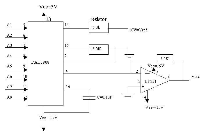
Signal conditioning involves a series of operations applied to a signal to make it compatible for interfacing with other devices or systems. Signal conditioners are the devices that execute this operation, featuring both an input and an output. Typically,...
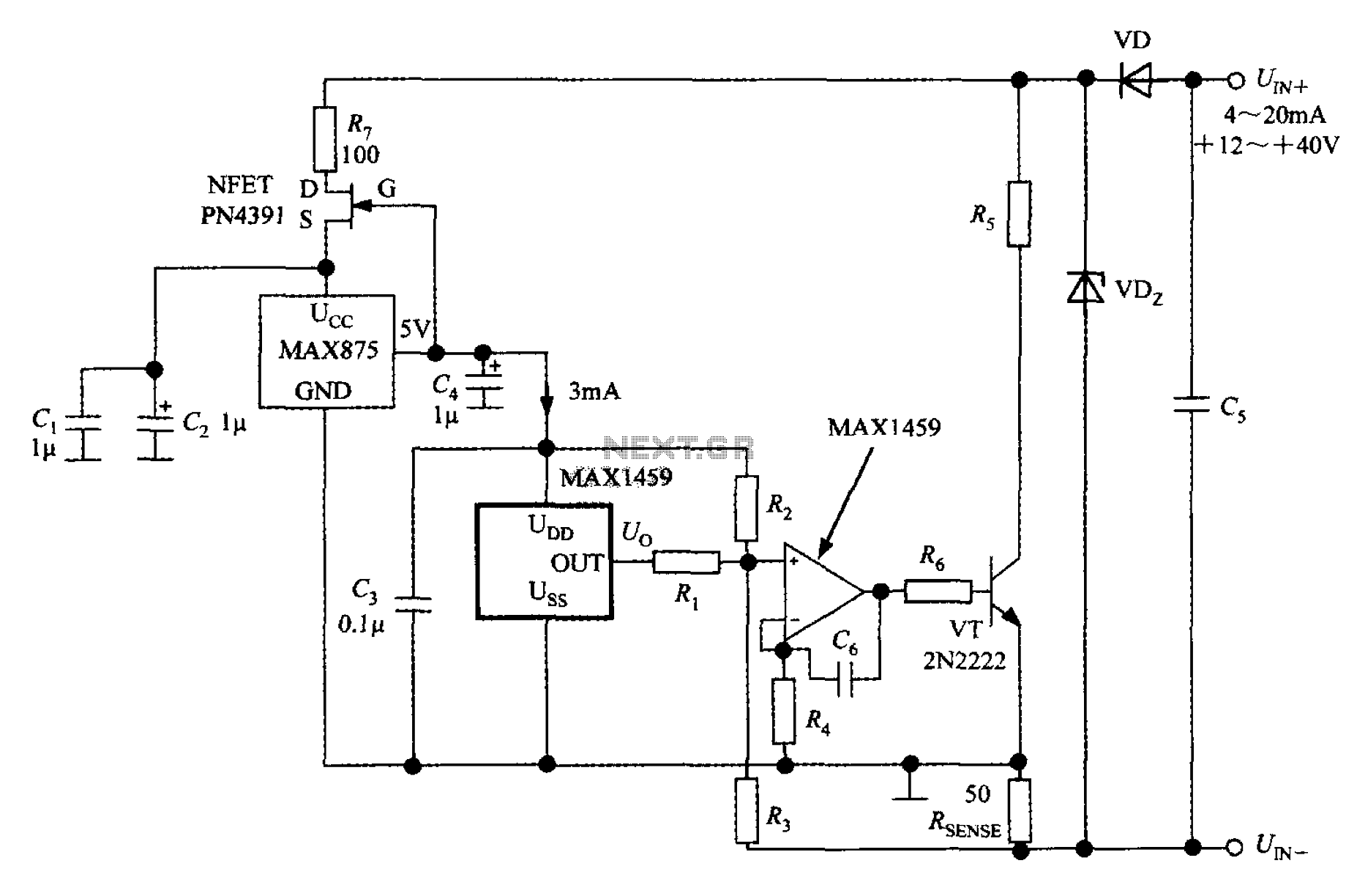
A 4 to 20 mA current transmitter circuit is implemented using the MAX1459, as illustrated in the accompanying figure. The output voltage from the programmable gain amplifier (PGA) is supplied to a spare amplifier chip, and subsequently, an external...
This automatic NiCd charger for 9V NiCd batteries utilizes the properties of a 555 timer and is straightforward to construct. The design allows for continuous charging of the battery without the risk of overcharging or discharging. With the specified...
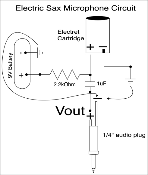
A condenser microphone (electret type with two terminals) is to be powered. A resistor of 1 kΩ and a capacitor of 10 µF have been connected to its positive terminal, while the other terminal is grounded. To power an electret...
This circuit diagram illustrates the conversion of a speaker into a microphone. When sound waves impact the diaphragm of a speaker, fluctuations occur in the coil, generating an induced voltage. This induced voltage is typically substantial but low in...
This is a battery tester circuit. This circuit is used to indicate whether the level of a battery voltage is normal, under-voltage, or over-voltage. The battery tester circuit is designed to assess the voltage level of a battery and provide...