
Drying the motor winding circuit current imbalance

The circuit diagram is designed to monitor the current flowing through the windings of a motor used in drying applications. This imbalance detection is crucial for ensuring the motor operates efficiently and safely. The schematic typically includes current sensors, which can be Hall effect sensors or shunt resistors, connected to an operational amplifier (op-amp) configured as a differential amplifier. This setup allows for precise measurement of the current in each winding.
The output from the op-amp is then fed into a microcontroller or a comparator circuit. The microcontroller processes the current data and compares the values from the different windings. If an imbalance is detected, it can trigger an alarm or a shutdown mechanism to prevent damage to the motor.
Additionally, the circuit may include indicator LEDs to provide visual feedback on the status of the motor winding currents. A power supply circuit is also essential to ensure that all components receive the necessary voltage levels for operation.
In summary, this motor winding current imbalance detection circuit is a critical component for maintaining the reliability and safety of drying motors, ensuring that they function within acceptable parameters and preventing potential failures due to uneven current distribution. Below is a circuit diagram of the motor winding current imbalance drying:
Related Circuits
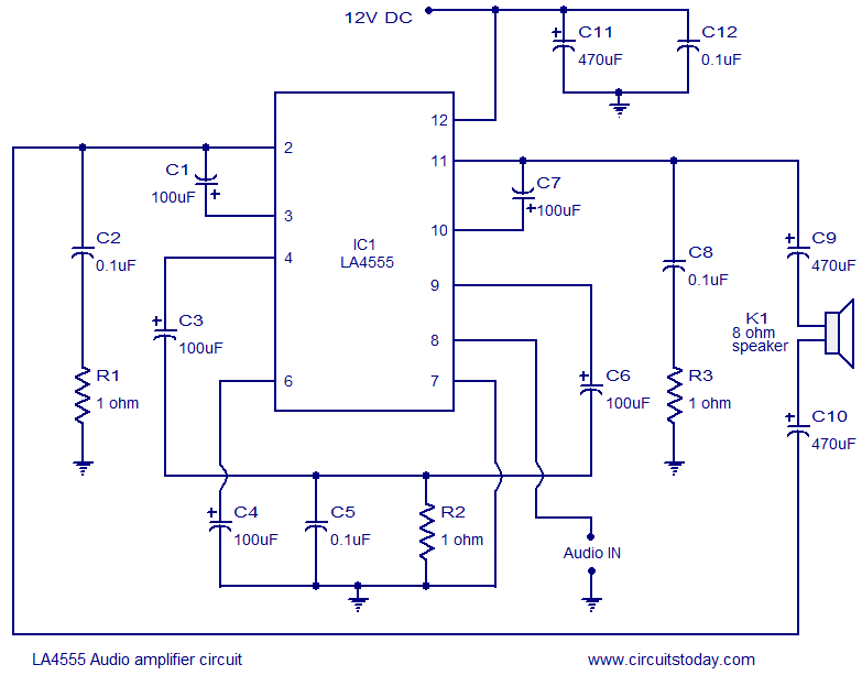
The LA4550 audio amplifier operates in a BTL (Bridge-Tied Load) configuration. This amplifier is capable of delivering 4W into an 8-ohm load when powered by a 12V power supply. The LA4550 is designed for audio amplification applications, particularly in situations...
This circuit is not entirely new, but it is straightforward, dependable, robust, and short-proof. It offers variable voltage up to 24V and adjustable current limiting up to 2A. Customization to meet specific requirements is possible, as detailed in the...
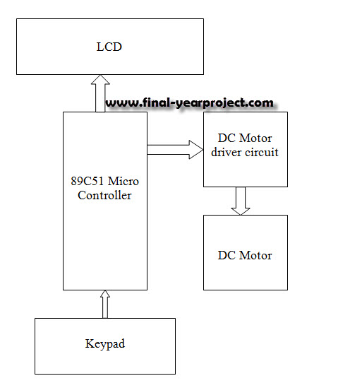
This report details an electronic project focused on the speed control of a DC motor using a microcontroller and PWM (Pulse Width Modulation). The system integrates a microcontroller with an LCD, keypad, and a DC motor driver. The microcontroller...
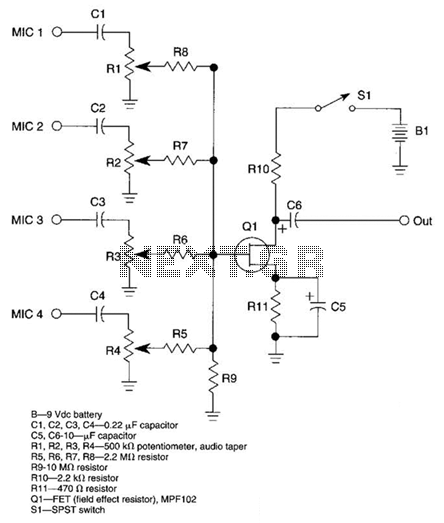
A JFET transistor is utilized as a high-to-low impedance converter and signal mixer. The input impedance is approximately 50.0 kΩ, which can be increased by adjusting resistors R5 to R8 up to 10 MΩ. The output impedance is around...
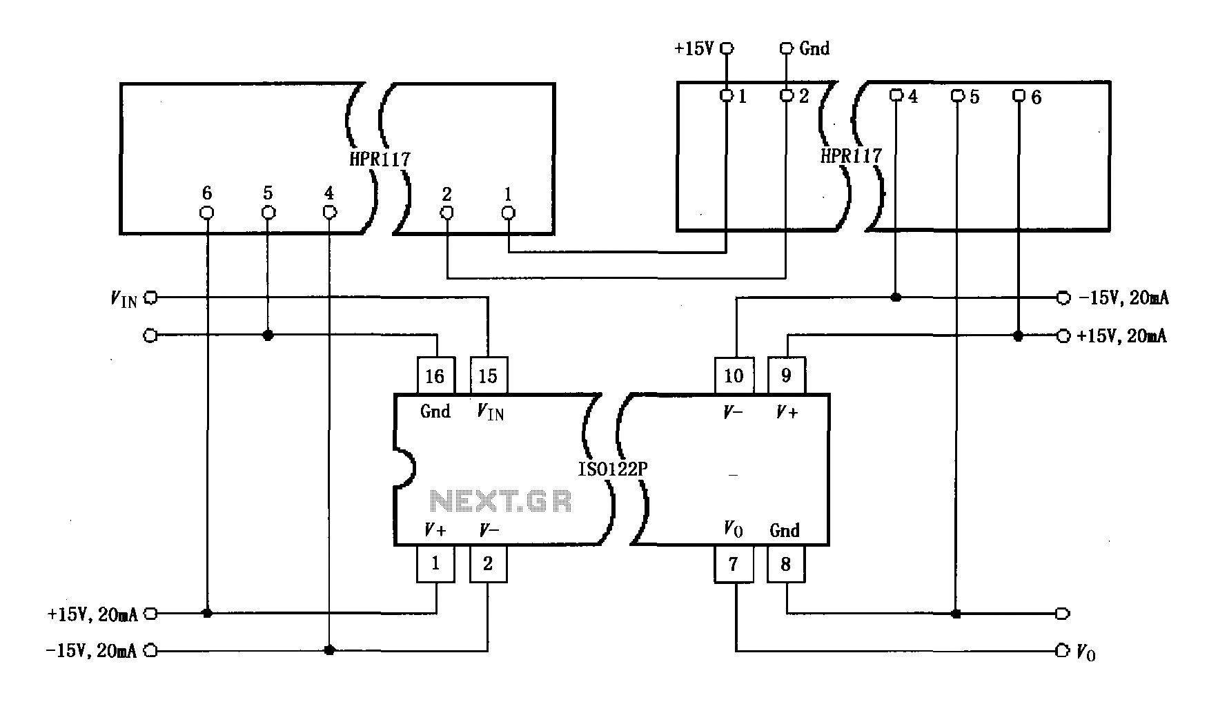
Power isolation is demonstrated for the ISO122P / 124, which features a three-port amplifier. The circuit also utilizes precision analog isolation amplifiers. The ISO122P / 124 isolation amplifier is a cost-effective solution, and the HPR117 DC/DC converter component provides...
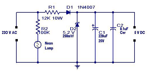
A simple transformerless power supply circuit with a diagram and schematics that provides a 5 volts DC output. This is a low-cost, low-current power supply circuit suitable for simple applications such as powering an LED. The transformerless power supply circuit...