
Speed Control of DC Motor using Microcontroller by using PWM ECE Project

The project utilizes the AT89C51 microcontroller, which is a widely used 8-bit microcontroller based on the MCS-51 architecture. It features a 4KB ROM, 128 bytes of RAM, and multiple I/O ports, making it suitable for various control applications. In this speed control application, the microcontroller's PWM capabilities allow for precise control over the motor's speed by adjusting the duty cycle of the PWM signal.
The system design includes several key components:
1. **Microcontroller (AT89C51)**: Acts as the central processing unit, generating PWM signals based on user input.
2. **LCD Display**: Provides a user interface for displaying the current speed of the DC motor and other relevant information. It is interfaced with the microcontroller to present real-time data.
3. **Keypad**: Serves as the input device for the user to set the desired speed of the DC motor. The keypad inputs are processed by the microcontroller to adjust the PWM signal accordingly.
4. **DC Motor Driver**: This component amplifies the PWM signal from the microcontroller to drive the DC motor. It ensures that the motor receives the necessary current and voltage for operation.
5. **DC Motor**: The actuator that converts electrical energy into mechanical energy, allowing for variable speed operation based on PWM input.
The PWM technique is employed to control the average voltage supplied to the motor, effectively regulating its speed. By varying the duty cycle of the PWM signal, the average power delivered to the motor can be controlled, resulting in precise speed adjustments. The block diagram of the system visually represents the interconnections among these components, highlighting the flow of signals and power.
In conclusion, this project serves as an excellent reference for understanding the implementation of speed control in DC motors using microcontrollers and PWM. It provides insights into hardware interfacing, programming, and the principles of motor control, making it a valuable resource for electronics students and professionals.This is a good Electronic project report on Speed Control of DC Motor using Microcontroller by using PWM. In this system, a micro controller is interfaced with a LCD, Keypad and DC motor driver. The Micro controller is used for controlling the DC motor by producing the PWM pulses. These pulse widths are produced according to the key pad register v alues which are allotted by MC. You can also Subscribe to FINAL YEAR PROJECT`S by Email for more such projects and seminar. In this project AT89C51 microcontroller is used as speed controller. In the above block diagram we are using one keypad, LCD, one driver circuit for DC motor and DC Motor. The report contains description of microcontroller and project with complete ALP programming. Use it for your reference and study work only. 🔗 External reference
Related Circuits
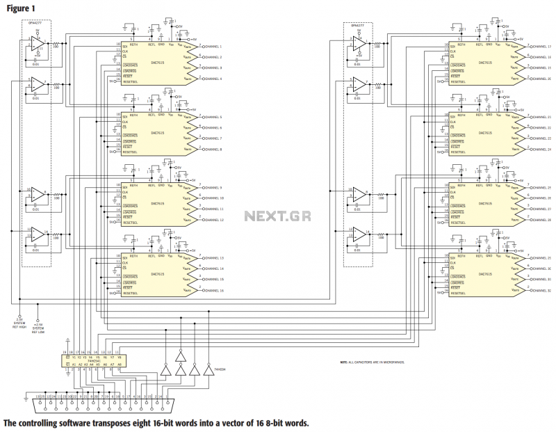
The circuit in Figure 1 controls 32 voltage-output channels from the parallel port of a PC. The circuit comprises eight DAC7615 quad voltage-output, serial-data programmable, 12-bit DACs. The controlling PC individually programs each of the 32 DAC channels, and...
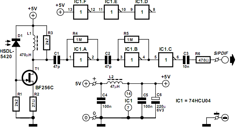
This simple circuit demonstrates unexpectedly effective performance when utilized with the IRS/PDIF transmitter mentioned elsewhere on this site. The IR receiver... This circuit is designed to work in conjunction with the IRS/PDIF transmitter, forming a robust system for infrared communication....
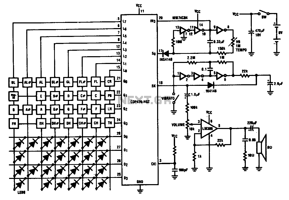
Twenty-five musical keys and 25 LEDs are provided to denote F to F" with half notes in between. Memory can store a played tune. There are ten preprogrammed tunes (each has an average of 55 notes) masked in the...
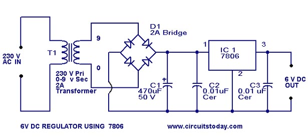
A simple 6-volt DC regulator circuit with a diagram and schematic using the 7806 IC, a positive voltage regulator. It serves as an elementary 6-volt, 1-ampere power supply circuit. The 7806 voltage regulator is a widely used integrated circuit that...
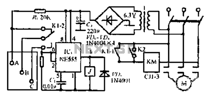
After the 3.40V power supply, the voltage is reduced to 6.3V through a full transition rectification using VDi and V sulfone. The C1 filter provides voltage stabilization after the caution circuit operates at the NE555 voltage level. When the...
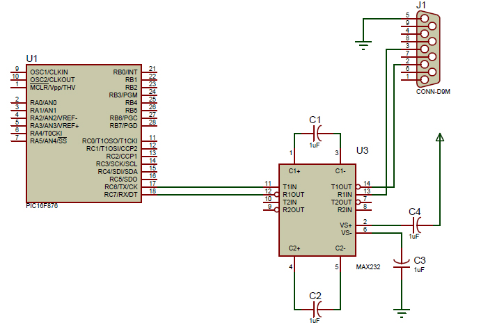
An introductory post on how to use serial communication in PIC Microcontrollers to send data to a PC. When considering serial communication, the primary thought is the transmission of data in a sequential manner. Until now, the focus has...