
DS Protocol (Data transfer via handshake)
")
While it is a little bit cumbersome, it is robust in that there is handshaking on each bit that is sent.
Each message is composed of a byte preceded by a flag bit. The purpose of the control bit is to indicate to the slave whether a command or data is being sent. When the flag bit is a logic 1, a command is being sent. When the control bit is a logic 0, data is being sent. This signaling system allows a simple register-based interface and command structure to be used. Additional details of the data format are shown in the Data Format section of this document. DS does not allow more than two devices to be connected to the same interface: one host and one slave. Since there is no mechanism defined for detecting and resolving collisions, the slave may only transmit when requested by the host.
Because of the sampling of the attention line by the sender, there is some uncertainty in the data transfer rate. Without delving into the theory, suffice it to say that some combinations of host and slave timing will result in particularly slow data transfer rates - on the order of minutes per byte have been observed. At very high speeds on some hardware, data transmission may be unreliable or fail completely. It is therefore a good idea to experiment a little bit and determine a transfer speed that proves reliable. It might be necessary to increase pull-up current in order to achieve high enough data transfer rates. Remember that this interface is intended for applications where transfer speed is not particularly important.
The DS protocol utilizes a straightforward yet effective method for communication between a host and a slave device using firmware-based control. The implementation requires minimal additional hardware, consisting primarily of two bidirectional I/O ports, which can serve dual functions as input or output depending on the configuration. The protocol operates by sending data and instructions in a sequential manner, with each byte accompanied by a control bit that distinguishes between command and data transmission.
In practical applications, the protocol's reliance on handshaking ensures that each bit is acknowledged before proceeding, enhancing reliability despite potentially slower data transfer rates. The system's design accommodates only one host and one slave, limiting complexity but necessitating careful management of communication timing to avoid delays.
Moreover, the protocol's adaptability to various microcontroller architectures, such as the Atmel AVR series, facilitates its integration into diverse electronic systems. The emphasis on simple register-based commands allows for easy implementation and debugging, making it suitable for low-speed applications where high data transfer rates are not critical. In summary, the DS protocol serves as a robust solution for interprocessor communication in environments lacking dedicated hardware interfaces, balancing simplicity with functional reliability.The DS protocol was designed to provide firmware-based bidirectional host-to-slave inter processor communications for situations in which no hardware solution is available and the host and/or the slave in incapable of tending the interface in real time. The only specialized hardware required is two bidirectional I/O ports on each chip (alternatively two input ports and two tri-statable output ports may be used).
When read, DS slaves conforming to the interface protocol appear as byte-wide two locations -one register for temporary storage of incoming data and one location for instructions. Instructions and data are send one byte at a time with each byte preceded by a control bit, which when set, indicates and instructions.
A cleared control bit indicates the following byte is data to be held in the Incoming Data Register until a later instruction byte tells the slave what to do with the data byte. DS messages are sent 9 bits at a time as one byte preceded by a control bit that indicates whether the byte following is meant to be stored in the Incoming Data Register or sent to the Instruction Interpreter.
In the flowcharts below, the control bit is located in the carry bit in both the sending and receiving routines. The flowcharts and code on this page were written with the Atmel AVR processors in mind, but should be easily ported to other processors.
The communications routines were coded directly from these flow charts. At the start of a bit transfer, the sender puts the data bit on the data line. After the data line has been given a chance to settle, the sender pulls the attention line low for some period of time. Periodically, it releases the attention line, waits for the line to settle, then peeks at the line to see if it is being held low by the receiver.
If the receiver is holding the line low, to indicate that it has received the data bit, the sender inverts the data line to acknowledge the receiver holding the attention line low. The receive, upon seeing the data line reverse, releases the attention line, and the sender, seeing the attention line being released, releases the data line.
That process concludes on bit transfer. While it is a little bit cumbersome, it is robust in that there is handshaking on each bit that is sent. Each message is composed of a byte preceded by a flag bit. The purpose of the control bit is to indicate to the slave whether a command or data is being sent. When the flag bit is a logic 1 a command is being sent. When the control bit is a logic 0 data is being sent. This signaling system allows simple register-based interface and command structure to be used. Additional details of the data format are shown in the Data Format section of this document. DS does not allow more than two devices to be connected to the same interface: one host and one slave.
Since there is no mechanism defined for detecting and resolving collisions, the slave may only transmit when requested by the host. Because of the sampling of the attention line by the sender, there is some uncertainty in the data transfer rate.
Without delving into the theory, suffice it to say that some combinations host and slave timing will result in particularly slow data transfer rates -on the order of minutes per byte have been observed. At very high speeds on some hardware data transmission may be unreliable or fail completely. It is therefore a good idea to experiment a little bit and determine a transfer speed that proves reliable.
It might be necessary to increase pull-up current in order to achieve high enough data transfer rates. Remember that this interface is intended for applications where transfer speed in not particularly important.
🔗 External reference
Related Circuits
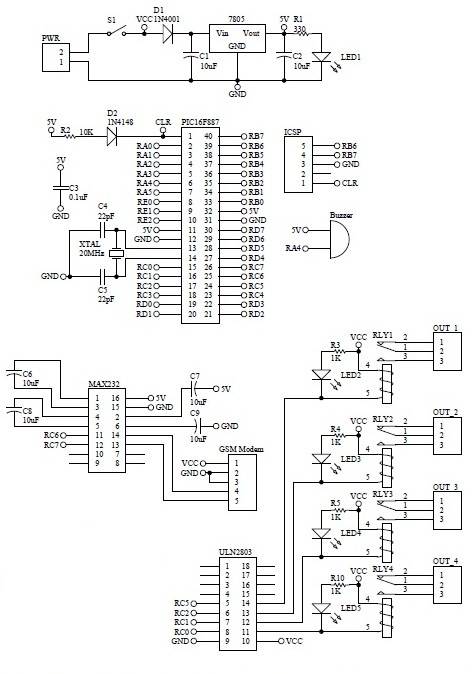
How to turn on equipment by sending SMS `1111` to switch it ON and switch off the equipment by sending SMS `0000`. The GSM switch will receive instructions for either load 1 (L1), load 2 (L2), load 3 (L3),...
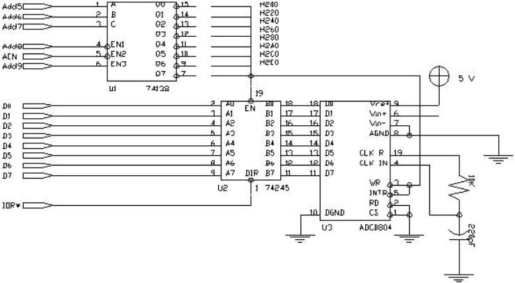
Chipmunk BASIC has many useful functions. A small BASIC file was created to read the serial port and plot the value on the screen (available upon request for free). The desktop 386SX PC is equipped with a 1.44MB floppy...
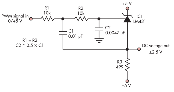
This simple circuit converts a 5V PWM signal into a variable precision reference voltage with a range of -2.5V to +2.5V. Many designs, such as a digitally controlled power supply or a programmable dummy load, require a Digital to...
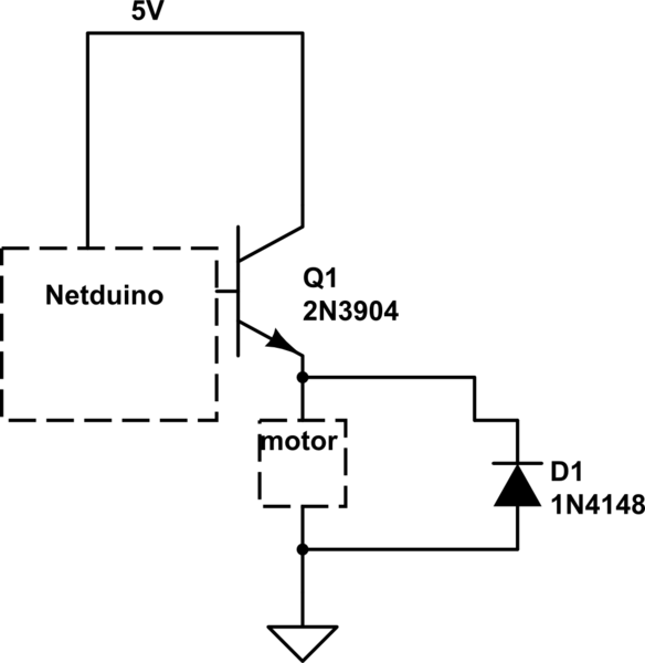
When the motor is connected in this manner, the Netduino activates the transistor, but nothing occurs. Swapping the motor with an LED results in the LED lighting up, indicating that the motor is not receiving sufficient power. Connecting the...
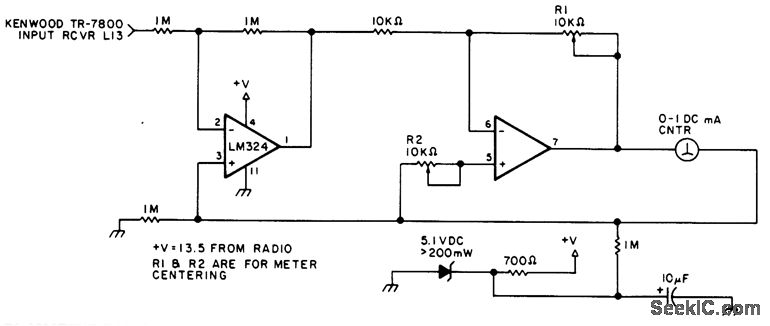
This circuit can be utilized in most FM VHF receivers, with the connection made from the FM discriminator. Each transmitted signal has a unique deviation signature, which can assist in identifying jammers. The described circuit is designed for integration into...
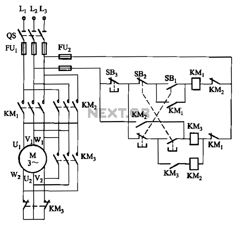
A hoist rated at 22kW and below is equipped with a power-saving Y-conversion circuit, as depicted in the figure. This circuit enhances the standard hoist design by incorporating a CJ20-10A exchange contactor. The implementation of the Y-conversion circuit during...