
Programmable Control For Home Safety via GSM Remote

The described system utilizes a GSM switch that allows remote control of multiple electrical loads via SMS commands. The operational commands are simple text messages: sending `1111` activates the desired load, while sending `0000` deactivates it. The system can manage four distinct loads, identified as Load 1 (L1), Load 2 (L2), Load 3 (L3), and Load 4 (L4).
The GSM switch is equipped with a GSM module that receives SMS messages sent from a mobile phone. Upon receiving a command, the module decodes the message and determines which load to control based on the specified command. Each load is connected to a relay that acts as a switch, allowing or interrupting the flow of electricity to the load.
The status of each load is monitored and reported back to the user. After processing the commands, the GSM switch sends SMS notifications indicating whether each load is currently ON or OFF. This feedback mechanism ensures that the user is informed of the operational state of their equipment.
The schematic for this system would typically include the following components: a GSM module, microcontroller (such as an Arduino or PIC), relays for each load, power supply circuits, and necessary protective components like diodes and fuses. The GSM module connects to the microcontroller, which interprets the incoming SMS commands and activates the appropriate relay to control the associated load. Each relay output connects to the respective load, allowing for safe operation of the electrical devices.
Overall, this GSM switch system provides a convenient and efficient method for controlling electrical equipment remotely, enhancing user accessibility and operational flexibility.How to turn on equipment by sending SMS `1111` ON `and switch off the equipment by sending SMS` 0000 GSM Switch will receive instructions either load 1 (L1), load 2 (L2), load 3 (L3) or load 4 (L4). Then the GSM Switch will send the four load status is ONor OFF either. Skematiknya are as follows 🔗 External reference
Related Circuits
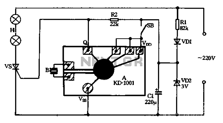
A 220V AC power supply is utilized through a resistor R1 to step down the voltage, followed by a rectifier VD1 and a filter capacitor C1, resulting in an output voltage of approximately 3V DC for the KD-1001 manifold....
This circuit is used to convert a mono audio signal into a stereo signal that can be panned between the left and right channel by a 0-10V control signal, it is intended for analog synthesizer systems. The circuit is...
Here is a simple project that sends continuous or switch controller MIDI messages that correspond to the position of a potentiometer. Given a few parts and a cannibalized volume or wah-wah pedal, you can build this MIDI controller pedal...
The Maxim MAX 6665 provides a complete temperature-dependent fan controller. It can switch fans operating at voltages of up to 24 V and currents of up to 250 mA. The IC is available from the manufacturer in versions with...
Security is a prime concern in our day-to-day life. Everyone wants to be as much secure as possible. An access control for doors forms a vital link in a security chain. The Microcontroller based Home Security System can be...
This PWM controller circuit is suitable for managing small motors with a maximum current consumption of 2A. For higher currents, additional cooling is required. The PWM (Pulse Width Modulation) controller circuit is designed to efficiently control the speed of small...