
ds1307 lcd

To interface the Arduino/Atmega168 microcontroller with an LCD display and a DS1307 Real-Time Clock (RTC), the following steps outline the necessary connections and programming considerations.
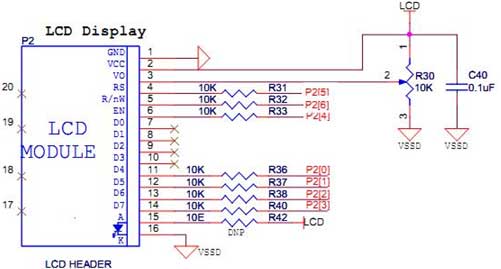
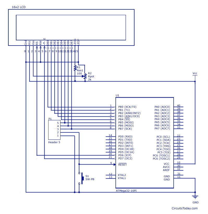
The LCD display typically used is a 16x2 character LCD, which operates using the HD44780 driver. The connections from the Arduino to the LCD include:
1. **Power Connections**: Connect the VSS pin of the LCD to the ground (GND) of the Arduino. The VDD pin should be connected to the +5V output of the Arduino. The VO pin, which controls the contrast, can be connected to a potentiometer to allow for adjustment.
2. **Control Pins**: The RS (Register Select) pin should be connected to a digital pin on the Arduino, commonly pin 12. The RW (Read/Write) pin can be connected to ground if only writing to the LCD. The E (Enable) pin should be connected to another digital pin, often pin 11.
3. **Data Pins**: The data pins D0 to D7 on the LCD can be connected to digital pins on the Arduino. A common configuration is to connect D4 to D7 to digital pins 5 to 2, respectively, for a 4-bit mode operation, which reduces the number of required pins.
For the DS1307 RTC, the connections are as follows:
1. **Power Connections**: The VCC pin of the DS1307 should be connected to the +5V from the Arduino, and the GND pin should be connected to the ground.
2. **I2C Connections**: The SDA (Serial Data Line) pin of the DS1307 should be connected to the A4 pin on the Arduino, while the SCL (Serial Clock Line) pin should be connected to the A5 pin.
Programming the Arduino involves including the appropriate libraries for both the LCD and the DS1307. The `LiquidCrystal` library is used for controlling the LCD, while the `RTClib` library is used to interface with the DS1307 RTC.
The code will typically initialize the LCD and the RTC in the `setup()` function. In the `loop()` function, the current time can be read from the RTC and displayed on the LCD. It is essential to ensure that the RTC is set to the correct time initially, which can be done using a separate sketch designed for setting the time.
This setup allows for real-time clock functionality alongside the ability to display information on an LCD, making it suitable for various applications such as digital clocks, timers, and data loggers.How to connect and program the Arduino/Atmega168 microcontroller to LCD display and DS1307 RTC.. 🔗 External reference
Related Circuits
Its an adaptation of the 2X 16 LCD project, by adding a ferrite loop antenna, two resistors, and a capacitor. Here the display shows the output of the 10 bit scanning voltmeter with Minimum Mass Wireless Coupler. Both the...
The PSoC 3 Primer Kit is specifically designed to assist students in mastering the necessary skills in embedded systems. The kit is structured to enable easy utilization of all possible features of the microcontroller. It supports the FX2LP Programmer,...
Interfacing an LCD display with AVR microcontrollers, specifically the Atmega8 and Atmega32, including a circuit diagram and embedded C code for implementation. The interfacing of an LCD display with AVR microcontrollers, such as the Atmega8 and Atmega32, is a common...
An LCD (liquid crystal display) is an electronically modulated optical device composed of multiple pixels filled with liquid crystals, arranged in front of a light source (backlight) or reflector to create images in color or monochrome. The block diagram...
This project provides a real-time clock utilizing the RTC chip DS1307. The DS1307 RTC chip features a built-in oscillator for timekeeping and includes its own registers for full functionality. The DS1307 is a low-power, I2C real-time clock that maintains accurate...

This page describes a cheap and simple yet flexible HDMI to parallel 3.3V interface. This allows connecting most LCD frames to the BeagleBoard without any further interface required. It is used with some 7-inch 800x480 displays running Angstrom Linux...