
DTMF coding multiple-channel infrared remote control switch circuit

The DTMF codec is integral to the functionality of the multiple-channel infrared remote control switch circuit. This circuit utilizes the dual-tone multi-frequency signaling method to transmit control signals over infrared light, allowing for the remote operation of various devices.
The infrared remote control signal emitter generates modulated infrared signals that carry DTMF tones. These tones are transmitted to the receiving end, where the infrared receiving signal amplifier boosts the incoming signals for better processing. The amplified signals are then sent to the DTMF signal decoder, which interprets the dual-tone frequencies and converts them into binary data corresponding to the specific commands.
Following the decoding process, the 12-channel data decoding distributor takes the binary data and routes it to the appropriate output channels. Each channel can control a different device or function, enabling the user to manage multiple devices seamlessly with a single remote control unit. The design of this circuit emphasizes efficiency and reliability, making it suitable for various applications, including home automation and industrial control systems.
Overall, the integration of the DTMF codec within the infrared remote control switch circuit enhances its versatility and functionality, allowing for a sophisticated control mechanism that is both user-friendly and effective.The DTMF codec is the abbreviation of the dual-tone multi-frequency codec. The multiple-channel infrared remote control switch circuit which is composed of the DTMF is as shown in the figure. It is composed of the infrared remote control signal emitter, the infrared receiving signal amplifier, the DTMF signal decoder, the 12-channel data decoding distributor..
🔗 External reference
Related Circuits
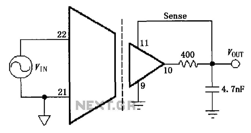
The ISO103 ripple reduction circuit features an output circuit combined with an RC high-pass filter designed to filter out output ripple without impacting the direct current (DC) characteristics. Under specific conditions, the circuit is capable of reducing an 800...
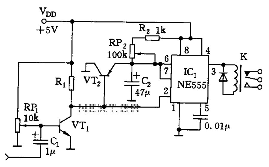
The circuit consists of a sound detection circuit and a monostable trigger circuit that activates a relay. VT1 amplifies the input audio signal. When a signal is detected, the 555 timer is triggered, pulling K. Simultaneously, VT2 conducts, allowing...
Many applications require a large number of keys connected to a computing system. Examples include PC keyboards, cell phone keypads, and calculators. Connecting a single key to a microcontroller unit (MCU) is straightforward; however, connecting 10 or 100 keys...
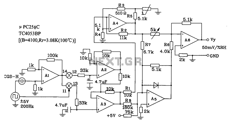
CGS-H ceramic humidity sensor constructed low humidity detection circuit diagram. The CGS-H ceramic humidity sensor is designed to detect low humidity levels within a specified range. This sensor operates on the principle of changes in capacitance that occur with variations...
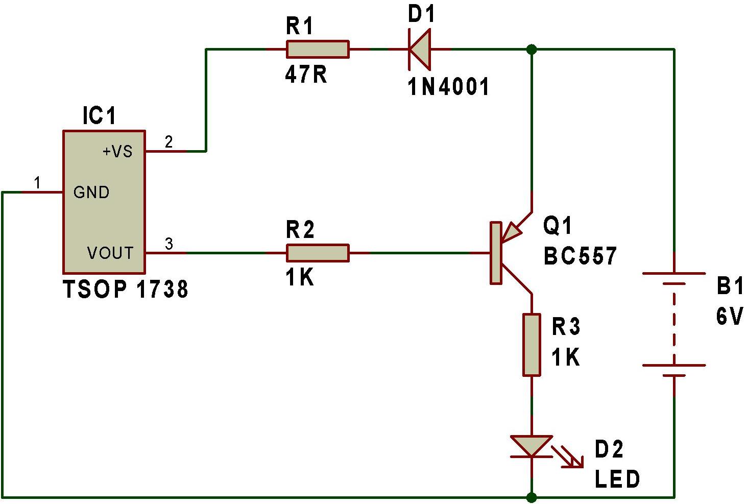
The remote tester circuit operates similarly to a dark sensor using a BC557 transistor. An LDR has been substituted with an IR sensor, specifically the TSOP 1738. The circuit functions as a remote tester; when a remote control switch...
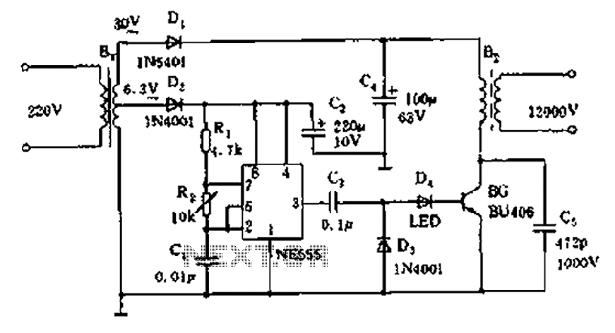
The neon voltage power supply circuit is straightforward to construct, offering stable output power and other desirable characteristics. The core component of this circuit is the NE555 timer, which generates a high-frequency oscillation signal in the range of 15...