
ISO103 ripple reduction circuit diagram

The ISO103 is a precision instrumentation amplifier that is often utilized in applications requiring low noise and high accuracy. The ripple reduction circuit is particularly crucial in scenarios where power supply noise can adversely affect signal integrity. The incorporation of an RC high-pass filter serves to eliminate unwanted AC ripple components from the output while maintaining the DC level.
The circuit typically consists of a resistor (R) and a capacitor (C) arranged in series, with the output taken across the capacitor. The values of R and C are chosen based on the desired cutoff frequency, which is calculated using the formula:
\[ f_c = \frac{1}{2\pi RC} \]
where \( f_c \) is the cutoff frequency. For an 800 kHz ripple voltage, the filter must be designed to effectively attenuate frequencies around this value while allowing the DC component to pass through with minimal attenuation.
In practical applications, the selection of R and C will depend on the load conditions and the acceptable ripple voltage at the output. Careful consideration is required to ensure that the RC time constant is appropriate for the expected signal dynamics. The performance of the circuit can be further optimized by selecting components with low tolerances and temperature coefficients to ensure stability over varying operating conditions.
Overall, the ISO103 ripple reduction circuit with an RC high-pass filter is an effective solution for minimizing ripple voltage in sensitive electronic applications, ensuring that the DC output remains stable and reliable. As shown for the ISO103 ripple reduction circuit. Circuit at the output plus an RC high-pass filter for filtering output ripple bang, without affecting the current (DC) feature conditions 800kHz ripple voltage can be reduced to 5mVp-p.
Related Circuits
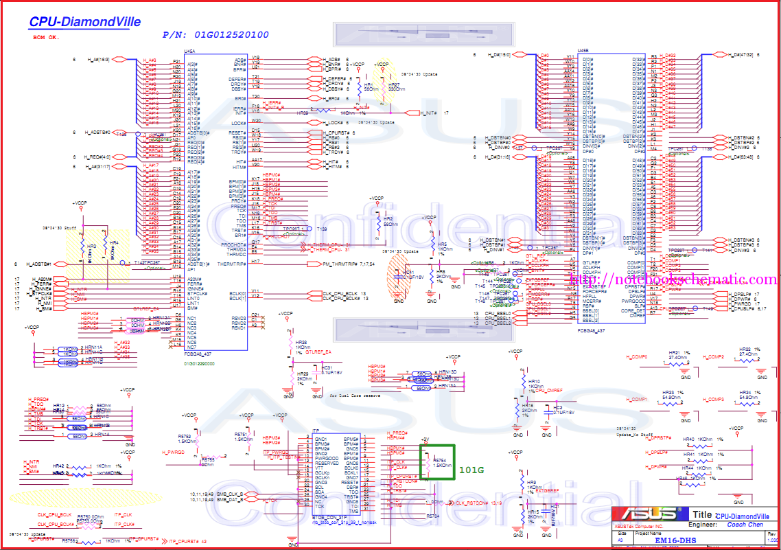
Laptop schematic circuit diagram for laptop repair and laptop BIOS password removal. The laptop schematic circuit diagram serves as a crucial resource for technicians and engineers involved in laptop repair and maintenance. This diagram provides a detailed representation of the...

The circuit is a high-power car audio amplifier schematic. It functions as a car audio amplifier using the PA02 and LH0101 integrated circuits (ICs). Each IC delivers an output power of 30W with an 8-ohm impedance. The part list...
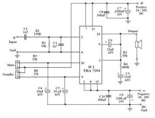
This audio amplifier circuit utilizes the TDA7294, a power integrated circuit designed for high-quality audio applications. The TDA7294 operates as a class AB amplifier, characterized by low noise and distortion levels, a wide bandwidth, and robust output current capability....
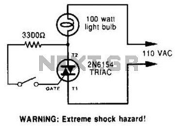
A triac can be utilized as a line-operated AC power switch that directly controls lamps, heaters, or motors. A brief current pulse into the gate activates the triac, and it remains on until the main current reverses. A triac, or...
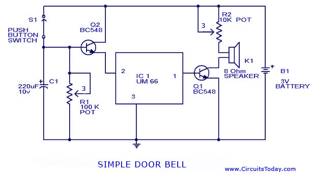
A simple doorbell circuit diagram and schematic designed using the UM66 IC, which is a music sound generator. This is an easy-to-make electronic doorbell circuit. The doorbell circuit utilizes the UM66 integrated circuit, known for its capability to generate musical...
Integrated circuit gates IC1-a and IC1-b form a monostable multivibrator, whose time constant is determined by capacitor C2 and resistor R3. When the transmitter is dekeyed and then almost immediately rekeyed, point TX+ goes low, causing pin 1 to...