
DTMF Decoder Relay Driver

The circuit described integrates several components to achieve reliable control of relays based on DTMF tone detection. The Motorola MC145436 DTMF decoder is central to the system, providing the necessary signal processing to recognize DTMF tones from the audio input. This decoder is clocked by a stable 3.58 MHz crystal oscillator, which ensures consistent timing for the DTMF detection process. The output from the decoder signals the Atmel AT90S2313 microcontroller to wake from sleep mode, allowing it to process commands.
The microcontroller's lack of a built-in brown-out detector necessitates the use of the MC34064 reset generator. This component monitors the supply voltage, ensuring that the microcontroller resets appropriately to avoid EEPROM corruption when voltage levels drop. The circuit also features a ULN2803 driver to manage the control of multiple relays, allowing for expanded functionality while maintaining the ability to handle multiple outputs without exceeding the microcontroller's current limitations.
The DTMF command structure is designed for simplicity, with commands initiated by a [*] and terminated by a [#]. This structure facilitates easy command recognition and execution, while the tone buffer allows for temporary storage of commands until they can be processed. The system's pulse output mechanism, which toggles relay states with defined timing, ensures that commands are executed reliably without overlap or interference from additional DTMF signals.
The vulnerabilities associated with plaintext PIN transmission and potential replay attacks highlight the need for enhanced security measures. Implementing a rolling code system could provide an effective solution, although it would introduce complexity into the command structure. Exploring the capabilities of microcontrollers like the ATmega8 could lead to a more streamlined design, integrating DTMF decoding and brown-out detection into a single component, thus simplifying the overall circuit architecture while maintaining functionality.Following a power interruption, all relays assume their previous state before the power interruption. (relay states and PIN are stored in non-volatile memory) An Motorola MC145436 DTMF decoder is used, this IC is clocked with a common 3.
58Mhz NTSC colour burst crystal and supplies a divide by 8 clock output (about 450 Khz) which is used as the clo ck for the Atmel AT90S2313 microcontroller. As this MCU does not have a "brown out detector" feature, a MC34064 is used as a reset generator to prevent possible EEPROM corruption at abnormally low supply voltages. Audio from the radio RX is fed to pin 7 of the DTMF decoder. When the DTMF decoder detects a valid DTMF tone, it outputs a nibble representing the tone on pins 1, 2, 13 & 14 and it drives pin 12, it`s Data Valid output, high, which drives pin 11 on the mcu high.
This wakes the mcu up from sleep mode, and the mcu samples the nibble on it`s input pins 2, 3, 6 & 7. Depending on the sequence of DTMF tone data supplied to the mcu, the mcu uses it`s pins 12 - 19 as outputs to control the relays, these outputs are fed to a ULN2803 open collector driver IC, which drives the output lines.
All DTMF commands sequences start with a [*] and end with a [#]. Decoded DTMF tones are stored in a tone buffer, the command in this buffer is executed when the DTMF tone for the [#] key is received. Reception of the DTMF tone for the [*] key will clear the buffer without executing it. When a relay is pulsed, it will change state (XOR operation), wait about one second, then change back to it`s original state and if more than one pulse is being generated, there will be an approximately one second delay between each pulse.
During pulse output, the controller is deaf to incoming DTMF tones and you must wait for the end of the pulse sequence (maximum of about 20 seconds for a 10 pulse command) before sending another command. PIN is sent over the air as plaintext and this is vulnerable to interception. Also is vulnerable to a simple replay attack with a recording/playback device. A rolling code type authentication system might be the answer to this but then the commands will be more complicated - probably too complicated to keep in your head.
An ATmega8 or similar has a brown-out detector on die and could probably decode the DTMF tones in software (Goertzel algorithm, etc) - thus eliminating both the MC34064 reset generator and MC145436 DTMF decoder ICs. 🔗 External reference
Related Circuits
Touch screens are increasingly popular, yet many developers have never designed one. This guide provides a step-by-step approach to the necessary hardware and software for successful touch screen implementation. Touch screens are ubiquitous in industrial control systems, consumer electronics,...

This light-activated relay circuit utilizes the 555 timer integrated circuit (IC) and a light-dependent resistor (LDR) to create a light-sensitive relay suitable for applications such as intruder alarm systems or automatic lamp control at sunset and sunrise. The potentiometer...
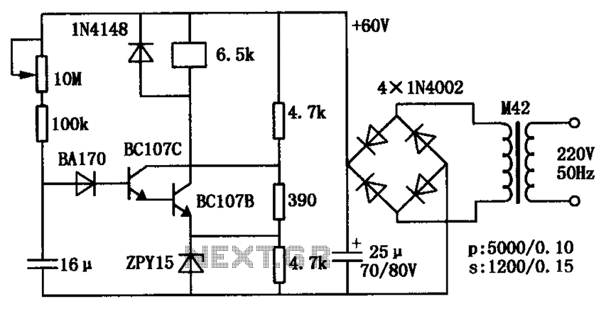
The circuit consists of a transistor relay delay pull mechanism. Initially, with a 16 µF capacitor at zero voltage, both transistors are off, and the relay remains inactive. As the 16 µF capacitor charges over time, the voltage increases...
The SL517 is designed as an audio, RF, or infrared decoder circuit suitable for electronic toy applications. The internal circuitry consists of an analog amplifier, a frequency divider, a bistable circuit, and a driver. It utilizes CMOS technology, has...
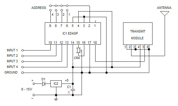
The Glolab ED4GP microprocessor-based Encoder/Decoder is designed for use with wireless modules, infrared remote controls, and other devices that operate with serial input and output data. It can function as either an encoder or a decoder by connecting pin...
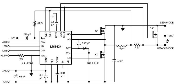
The LM3434 adaptive constant on-time DC/DC buck (step-down) constant current controller can be used to design a simple high-power LED driver application. The LM3434 provides a constant current for illuminating high-power LEDs. The output configuration allows the anodes of...