
Light Activated Relay with 555 Circuit

The light-activated relay circuit operates on the principle of comparing the voltage levels at the threshold pins of the 555 timer. The circuit is designed with two reference voltage levels: one at 1/3 Vcc and the other at 2/3 Vcc. The LDR serves as a variable resistor whose resistance decreases with increasing light intensity, allowing for precise control over the relay operation. The inclusion of the potentiometer R1 allows fine-tuning of the circuit's sensitivity to light changes, ensuring reliable performance in varying ambient light conditions.
In operation, when the ambient light level drops, the resistance of the LDR increases, causing the voltage at the threshold pin to rise. Once this voltage exceeds 2/3 Vcc, the output of the 555 timer switches from high to low, energizing the relay coil. This action can be used to trigger an alarm or turn on a light, depending on the application. Conversely, when the light level increases, the LDR's resistance decreases, and the voltage at the threshold pin drops below 1/3 Vcc, returning the output to a high state and deactivating the relay.
The addition of resistor R2 is a crucial design aspect that enhances stability by adjusting the hysteresis of the circuit. This resistor ensures that the relay does not rapidly switch on and off due to minor fluctuations in light levels, which could cause unwanted activation or deactivation. Careful selection of R1 and R2 values, along with the appropriate relay specifications, will ensure the circuit functions effectively in its intended application. The circuit can be powered using a suitable DC power supply that matches the relay's voltage rating, ensuring safe and reliable operation.This light activated relay circuit presented here uses the 555 timer IC and a light dependent resistor or LDR to form a light sensitive relay in an intruder alarm system or for switching on a lamp at Sun set and off at Sun rise. Potentiometer R1 value must be chosen and then adjusted that under normal conditions when the light is falling on the LD
R the voltage across the LDR is less than 1/3 of Vcc. The output of the 555 IC is high now. The actual value of R1 will depend on the resistance of the LDR. When the light fades or is interrupted by an intruder, the voltage across it rises above 2/3 of Vcc, tripping the IC flip-flop. The output goes low activating the relay. When the light is restored, voltage falls below 1/3 of Vcc, again tripping the flip-flop causing the output to go high and the relay drops.
The difference of 1/3 of Vcc between turning on and turning off voltages prevents relay chatter. This differential can be reduced by connecting a resistor R2 shown dotted in the schematic. Its value is about one and a half times of the LDR resistance in its illuminated condition. Use a 6V or 12V relay with a current of 200mA max. 🔗 External reference
Related Circuits
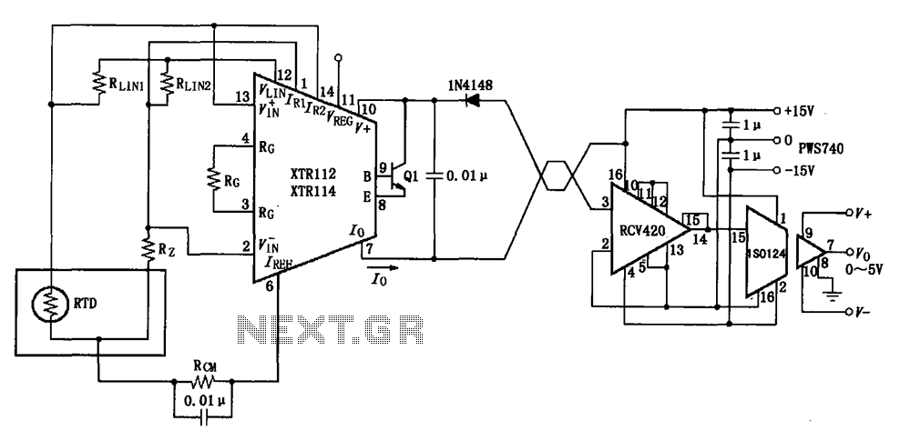
The RTD temperature data collected at the scene is converted into a voltage using the XTR112/114. This voltage is further transformed into a 4 to 20 mA current output, which is then transmitted via a twisted pair. The RCV420...
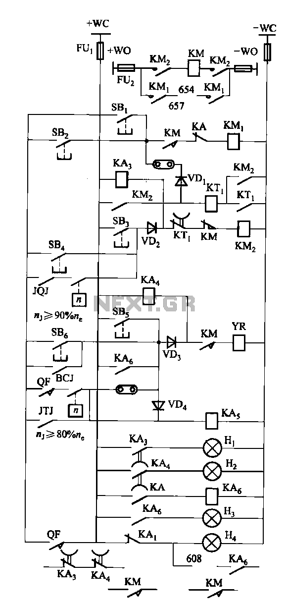
The FKL-32 type automatic thyristor excitation device is designed for synchronous generators with a terminal voltage of 400V and a capacity of 500kW and below. It is used for the automatic adjustment of excitation. The FKL-32 thyristor excitation device is...
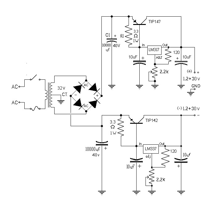
The 10A variable power supply circuit is symmetrical and can provide a symmetrical output voltage ranging from ±1.2 volts to ±30 volts DC, with a maximum current of 10A. This circuit utilizes symmetrical variable voltage regulators LM317 and LM337,...
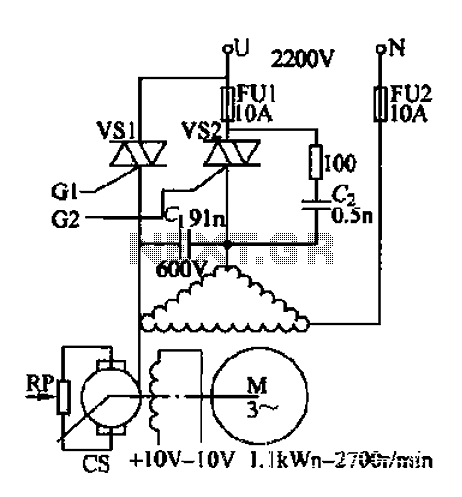
AC voltage is rectified by a bridge (VD1-VD4). A resistor (R1) limits the buck, while diode (VD5) provides clipping. A trapezoidal wave is generated as the trigger circuit for DC voltage and synchronization. When the base of transistor (VT1)...
This simple circuit drives six LEDs in a "Knightrider scanner mode." Power consumption primarily depends on the type of LEDs used, especially if a 7555 (555 CMOS version) is utilized. The circuit operates by sequentially illuminating the LEDs to create...
In certain applications, the current from a non-rectified voltage power supply circuit is insufficient. A light-emitting diode (LED) rectifier circuit can be employed to address this issue, serving as a power indicator. It is important to ensure that the...