
Length 1 minute delay relay pull transistor circuit diagram

The described circuit employs a transistor-based relay delay mechanism, which is useful in applications requiring a timed activation of a relay. The circuit begins in a dormant state, with the 16 µF capacitor initially uncharged, resulting in both transistors being in the off state. This lack of current flow prevents the relay from engaging.
As the circuit is powered, the capacitor begins to charge through the connected resistive elements. The charging rate is influenced by the resistor values in the circuit, particularly the 10 MΩ resistor, which serves as a timing element. By altering this resistor's value, the delay time before the relay is activated can be fine-tuned, allowing for versatility in timing applications.
Once the voltage across the capacitor reaches a predetermined threshold, both transistors are triggered into the on state. This action allows current to flow through the relay coil, thus engaging the relay. The relay's activation can be used to control larger loads or other circuits, making this a practical solution for various electronic applications where delayed activation is necessary.
The maximum delay of 60 seconds is significant for applications that require a prolonged waiting period before activation, such as in timing circuits, automation systems, or safety interlocks. The simplicity of the circuit design, combined with the adjustable delay feature, makes it an effective solution for creating controlled timing sequences in electronic systems. Proper selection of the capacitor and resistor values is crucial for achieving the desired operational characteristics. As shown is composed of a transistor relay delay pull circuit. Just power, 16 F capacitor voltage is zero, two transistors are off, the relay does not operate. With 16 F capaci tor charge, over a period of time to which the voltage reaches a high level, two transistors are turned on, the relay delay pull. The delay time of up to 60s. Delay time can be adjusted by 10M resistor.
Related Circuits
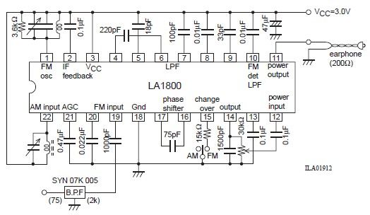
This portable AM/FM radio circuit is designed using the LA1800 integrated circuit (IC) along with several external components. The LA1800, manufactured by Sanyo Semiconductors, requires only a few additional components for its operation. The output signal is directed to...
The enhancement circuit, as depicted, increases the high-frequency components of the video signal, thereby improving the contrast of the television image. It can be connected between the VCR and the TV SCART input. The circuit utilizes transistor T1 for...
This device emits intermittent beeping for approximately two seconds when a whistle is detected within a range of several meters. The first two inverters in IC1 function as audio amplifiers. IC1A consistently amplifies the signal captured by a small...

This circuit describes the sensing of air flow using the PIC16C781 microcontroller. It utilizes Programmable Switch Mode Controllers (PSMC) that combine an Integrated Operational Amplifier, a Digital-to-Analog Converter (DAC), and a gated timer to create a thermally operated air...
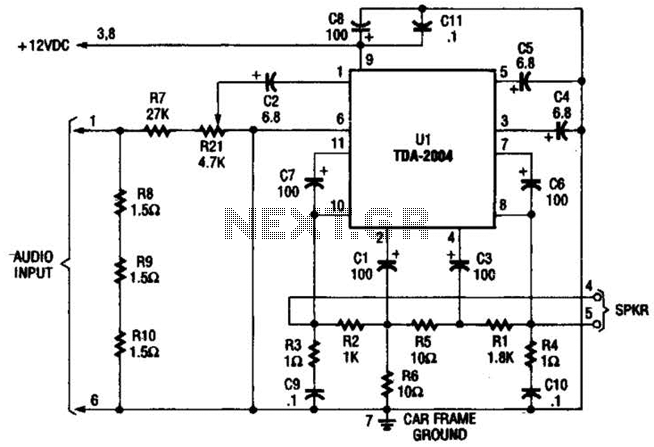
Only one channel of this circuit is shown. The other is practically identical. The input to the circuit, taken from the speaker output of a car radio, is divided into two paths. In one path, a high-power divider network...
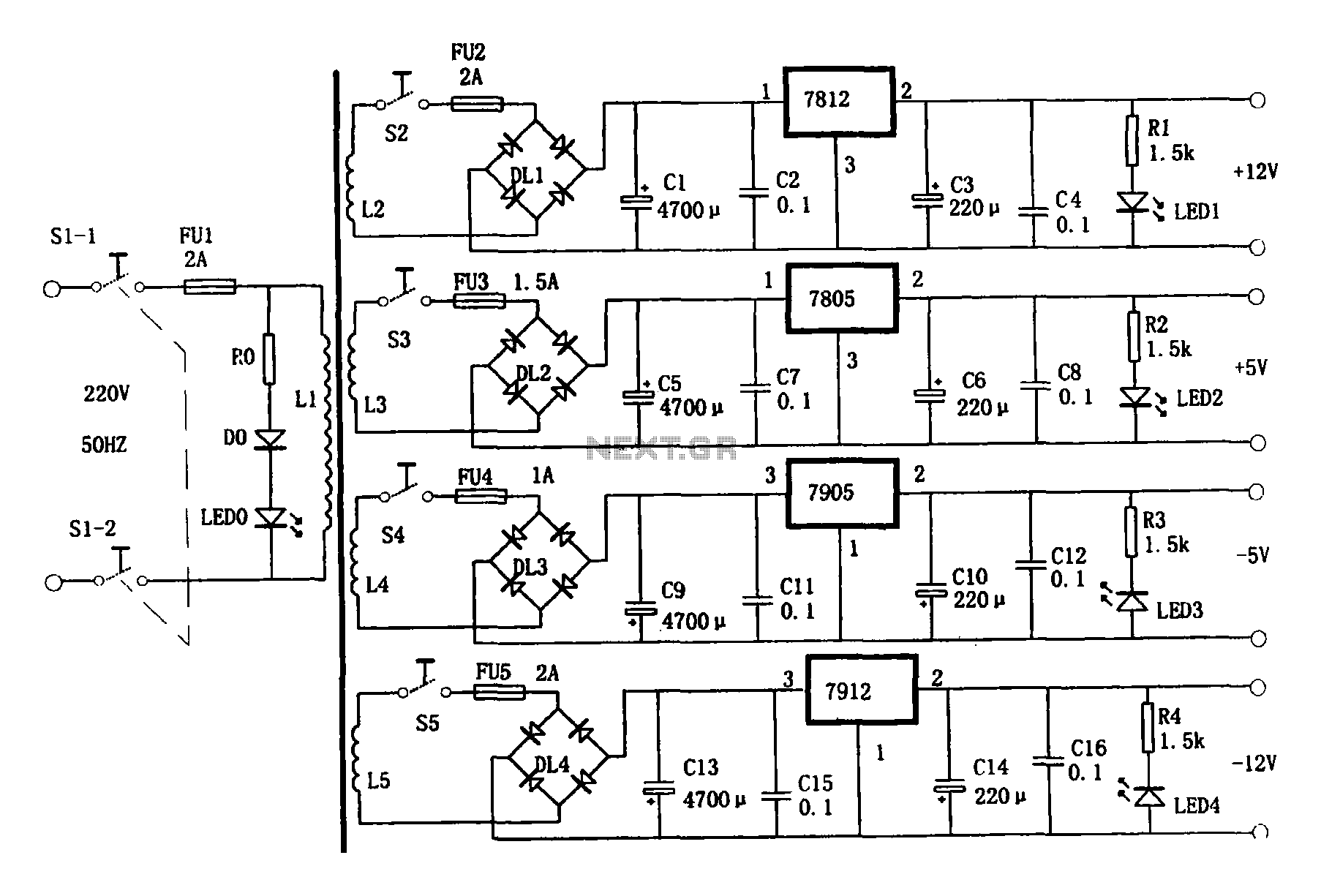
This document presents a multi-output power supply circuit. The circuit utilizes the secondary winding of a transformer and incorporates four voltage regulators: 7812, 7805, 7905, and 7912, providing independent output voltages of +12V, +5V, -5V, and -12V, respectively. Each...