
DTMF Remote Domestic System Control

The DTMF (Dual-Tone Multi-Frequency) Remote Domestic System Control Circuit utilizes DTMF signaling for remote operation of household devices. The circuit typically consists of a DTMF decoder, a microcontroller, and a relay driver circuit.
The DTMF decoder receives audio signals that correspond to specific DTMF tones, which are generated by a mobile phone or a DTMF keypad. Each tone represents a unique command, allowing the user to control various appliances such as lights, fans, and other electronic devices. The decoder converts these audio signals into binary signals that can be processed by a microcontroller.
The microcontroller interprets the binary signals and executes predefined commands based on the received DTMF tones. For instance, pressing a specific key on the DTMF keypad may turn on a light or activate a fan. The microcontroller is programmed to respond to these signals and control the output through a relay driver circuit.
The relay driver circuit acts as an interface between the microcontroller and the high-power appliances. It allows the microcontroller to switch on or off the appliances safely, as it can handle higher voltage levels than the microcontroller itself. Typically, this circuit includes transistors or opto-isolators to ensure that the microcontroller is protected from high voltages.
The overall system can be powered by a standard AC supply, which is then rectified and regulated to provide the necessary voltage levels for the microcontroller and other components. Additionally, the circuit may include indicators such as LEDs to provide visual feedback about the status of the appliances being controlled.
In summary, this DTMF Remote Domestic System Control Circuit offers a convenient and efficient way to manage household devices remotely, leveraging DTMF signaling technology for seamless operation.The following circuit shows about DTMF Remote Domestic System Control Circuit Diagram. Features: DTMF signals can be transmitted over a radio to .. 🔗 External reference
Related Circuits
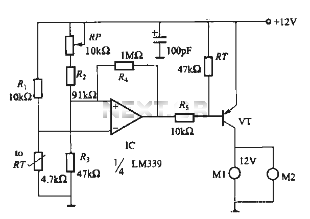
When running large-scale software or games, a computer's internal temperature can increase significantly, especially during hot summer months. Although the machine is equipped with a CPU and graphics card fan, poor hot air circulation prevents immediate removal of heat...
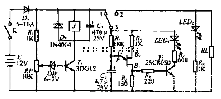
The discharge control circuit consists of a battery management system designed to prevent over-discharge of a battery. It features a relay control mechanism that activates when the battery voltage drops below a specified threshold of approximately 10.5V. The circuit...
Most recent cars are equipped with a significant amount of electronics, including ABS brake systems, engine control with injection calculators, airbag activation, and various comfort functions. One such function, often overlooked due to its commonality, is the automatic activation...

Many brands in Asia utilize ultrasonic remote control switch circuits, with some employing relays and others utilizing thyristors. The remote control transmitter is of a puffer type, featuring an ultrasound flute with both olive and flat circular shapes. This...
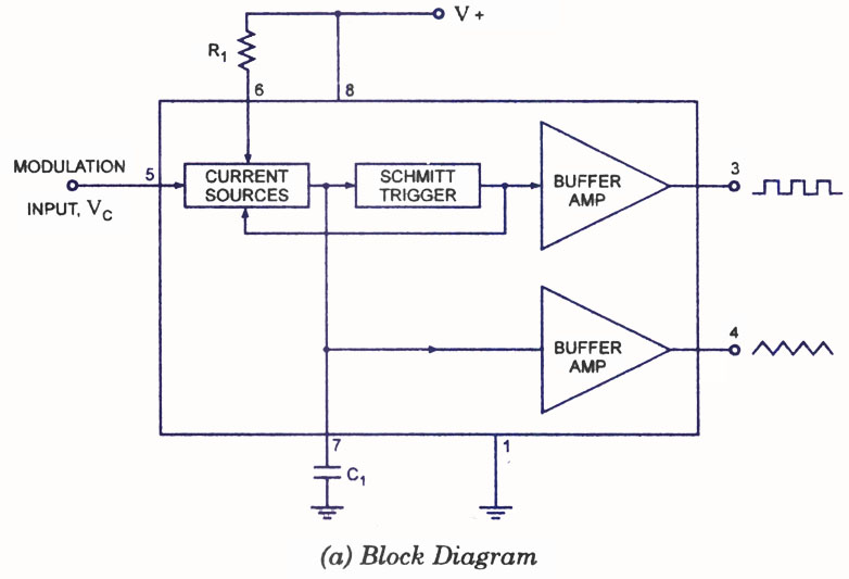
A voltage-controlled oscillator (VCO) is a type of oscillator in which the frequency of output oscillations can be adjusted by varying the amplitude of an input voltage signal. VCOs are commonly utilized in frequency modulation (FM), pulse modulation (PM),...

The Atmega8 microcontroller from Atmel features numerous digital and analog input/output lines, making it an ideal choice for developing various measurement equipment. It is essential to have the GCC AVR programming environment installed, as outlined in the article "Programming...