
Ultrasonic remote control switch circuit diagram

The ultrasonic remote control switch circuit operates by harnessing ultrasonic signals to trigger electronic components effectively. The circuit is designed to convert AC mains voltage into a usable DC voltage through a series of components. The buck converter (C1) reduces the voltage, while the rectifier diodes (VD1, VD2) convert the AC signal to DC. The filtering capacitor (C2) smooths the output, ensuring a stable voltage supply for the control circuit, which is essential for reliable operation.
The piezoelectric ultrasonic sensor (BM) detects ultrasonic signals emitted by the remote control. The resonance circuit formed by R2 and L enhances the sensitivity of the receiver, allowing it to respond to specific frequencies associated with the transmitter. The flip-flop configuration (VT3 and VT4) is crucial for processing the received signals and ensuring that the relay (VT5) operates correctly to control the connected load (CZ).
Troubleshooting involves assessing the performance of key components, particularly the capacitors (C1 and C2) and the LED indicator (VD7). A drop in mains voltage can lead to insufficient power supply, causing the relay to fail to engage properly. Regular maintenance ensures that capacitors are within operational specifications, as their degradation can significantly impact circuit performance.
The design emphasizes the importance of component selection, as the values of C5 can influence the response time of the circuit. A well-optimized circuit will balance the capacitance values to achieve a quick response while maintaining stability. This intricate interplay of components allows for effective remote control functionality, making it suitable for a variety of applications in consumer electronics.Many brands and Asia ultrasonic remote control switch circuit form, the control device to perform some use of relay; others use thyristors. The use of remote control transmitter puffer type sub ultrasound flute (which have olive and flat circular shape). In this paper, a typical circuit shown in the drawings, for example, it works Introduction and troubleshooting two cases. First, the circuit AC220V by C1 Buck, VD1, VD2 rectifier; C2, after VD3 filter regulator control circuit to receive operating power.
BM is a piezoelectric ultrasonic receiving sensor sub; R2, L constitute a sub ultrasonic resonance circuit; VT3, VT4 constitute flip-flop; VT5 relay K composition and execution control circuit; CZ is charged with the load sockets. Second, Maintenance Examples [Example 1] after receiving the transmitter remote control commands, and controlled VD7 indicator lamp blinks in rapid succession at the same time, and you will hear mechanical noise generated when the relay armature trembling, after one second, warble stop by control bulbs and VD7 simultaneously extinguished.
This failure often occurs in remote switching power supply circuit, when the mains voltage is lower than 180V or down capacitor C1 of insufficient capacity, both due to the DC power supply to the machine is not sufficient to provide the required operating current, resulting in the drive circuit and relay difficult to successfully enter the normal pull-state performance of sorption is not strong, like non-absorbent such as smoking. After measuring the mains is normal, then remove the C1, measured obtaining capacity 0.32 F, capacity has been significantly reduced.
Put a 0.47 F / 400V polyester capacitor, troubleshooting. In addition, if C2 failure (no capacity) will lead to the same symptoms in this case. [Example 2] at each remote control lights, LED bulbs have VD7 and controlled in order to enter the stable after several flashing light-emitting state. The trigger pulse generation circuit, R3 is the collector load resistor VT2 from R3 output a trigger signal; C5 to prevent misunderstandings hair.
Failure in this case C5, a substitution electrolytic capacitor 2.2 F / 16V after the fault is cleared. Practice has proved that, C5 ranges generally between 0.47 ~ 3.3 F compare properly. In general, the capacity of the election was large, remote control switch response time is relatively longer, shorter and vice versa.
Related Circuits
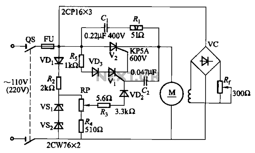
A 100W resistance-triggered motor control circuit designed for arc welding machines. It features an adjustment potentiometer (Rr) that can modify the DC motor excitation current. Additionally, a regulator (RP) is included to adjust the DC motor armature voltage, enabling...
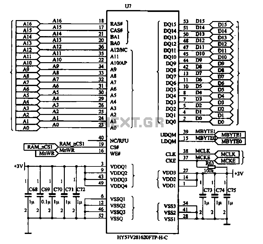
The Newman MP4 machine features three types of memory: data memory (U7), program memory (U8), and user memory (U9). Data memory is utilized for storing operational data, while program memory holds the machine's work program. User memory is designated...
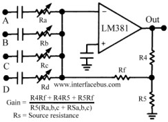
The circuit schematic below represents a method for designing an audio mixer. The active component is an LM318, although any operational amplifier could be used in its place. The circuit is a classic design for an operational amplifier summing...
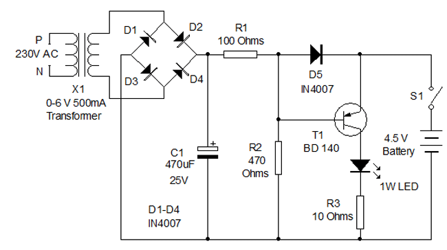
Circuit diagram for a mini emergency lamp. This mini emergency lamp activates during power failures to provide cool white light in the room. It utilizes a 1-watt white LED to deliver adequate illumination. The circuit for the mini emergency lamp...
Many of today's high-performance FPGAs, microprocessors, DSPs, and industrial/embedded subsystems require sequencing of the input power PS10 and PS11. Historically, this has been achieved through: i) discrete methods using comparators, references, and RC circuits; ii) expensive programmable controllers; or...

This Project Automatic Room Light Controller with Visitor Counter using Microcontroller is a reliable circuit that takes over the task of controlling the room lights as well as counting the number of persons/visitors in the room very accurately. When...