
Ten Road string lights flashing circuit

The circuit operates by generating a series of clock pulses that are fed into the CD4017 decade counter. Each pulse corresponds to a counting sequence, where the counter outputs a high signal sequentially from Q0 to Q9. This output is connected to the gates of the thyristors VT1 through VT10, which are configured to allow current to flow through the string lights when triggered. The design ensures that only one thyristor is activated at a time, resulting in a sequential lighting effect that creates the illusion of movement along the string of lights.
The clock pulse generator is critical for the operation of the circuit. The CD4060 IC serves as the primary oscillator, producing a square wave output that is fed into the NAND gates to create the necessary pulse train for the CD4017 counter. The frequency of the output can be adjusted using the potentiometer R1, allowing for fine-tuning of the flashing speed of the lights. This feature is particularly useful for applications requiring specific timing or visual effects.
The thyristors (MCR1.0) are selected for their ability to handle the current required by the string lights while providing reliable switching performance. The circuit's design does not impose strict requirements on the other components, allowing for flexibility in component selection as long as they meet the necessary electrical specifications.
In summary, this digital integrated circuit effectively manages a string of flashing lights through a combination of a decade counter, a clock pulse generator, and thyristor switching, resulting in a visually appealing lighting display that can be customized for various applications.Digital integrated circuit is composed of ten road flashing lights string controller that drives El- El0 ten road string lights flashing cycle. The same, A2 is the - mf sequenc er block ten count system decoder CD4017 digital integrated circuits, when (: I continued input terminal count pulse, the output terminal Qo - Q9 will in turn output high, so the thyristor VTl - VT10 by opening times, so lights El - El0 will in turn light cycle, in the visual sense of movement can be formed if t. E1 - Fl (J Nymphoides South Xiaotun using beads consisting of string lights, string lights and each of bulbs in the house to ask certain regulatory legal arrangement, will form a wider variety of visual effects.
clock pulse generator consists of Al (CD406cj) in two H NAND gate, whose O ~ feet and CR ~ -RP), ( 1: square wave oscillator constituting astable oscillation pulse output from the pin unravel again closed a non-plastic door, away from the direct final pin output terminal A2, namely the first CP ? feet, f} is the LI A2 the number of pulses, adjustment potentiometer RI, before the holiday may Benjamin oscillation frequency, thus h coup string lights El- E10 flow rate.
(J requires LBH 4.V La poly internal olefins capacitor .VTl - VTIO bite ffl MCR1.os type and other small sister Feng-way thyristor glance. spider string Fl-FlO power should be controlled ioow F. other components no special requirements.
Related Circuits

This panning circuit, also known as a panoramic control circuit, allows for the adjustment of the perceived position of a microphone's input across two output channels. This effect is frequently utilized in mixing consoles within recording studios. Panning enables...

This is a common circuit often found in various resources, yet it appears to be less prevalent in stompbox applications. The circuit utilizes an NPN JFET DC coupled with a PNP BJT. The FET provides a significantly higher input...
XP power plug, FU fuse, ST temperature control, T1 low-voltage transformers, S1, S2 door interlock switch, S3 threshold control switch, RT thermal sensor, K1, K2 relay, EL furnace light, M1 wheel motor, M2 fan motor, T2 high-voltage transformer, C...
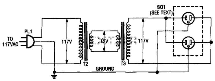
An isolation transformer for low-power applications (under 50 W) can be constructed using two 12-V filament or power transformers. This setup includes a standard duplex AC receptacle. It is important to utilize heavy-wire connections between the 12-V windings, as...

This infrared alarm barrier is designed to detect individuals passing through doorways, corridors, and small gates. The transmitter emits an invisible beam of infrared light. When this beam is interrupted by a person, a buzzer connected to the receiver...
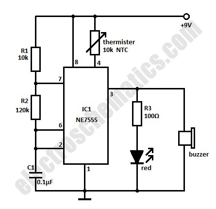
The high-temperature alarm will emit a beep and the LED will blink when the temperature of the device rises abnormally. This simple overheating alarm is designed to monitor heat levels. The high-temperature alarm circuit is an essential safety device used...