
Electronic Door Release circuit

The circuit primarily consists of a microcontroller, a keypad, a relay module, and a power supply. The microcontroller serves as the brain of the system, processing the input from the keypad and controlling the relay based on the entered code. The keypad allows the user to input a four-digit code, which is compared against a stored value in the microcontroller's memory.
When the correct code is entered, the microcontroller sends a signal to the relay module to energize it. This action closes the relay contacts, allowing current to flow to the door-release mechanism, which could be an electronic lock or similar device. The relay is configured to remain energized for a predetermined time, which can be adjusted based on the requirements of the application. After this time period, the relay will deactivate, cutting power to the release mechanism.
The circuit is designed with power efficiency in mind. The standby current is kept to a minimum, allowing the system to be powered by batteries for extended periods without significant drain. This feature makes it suitable for remote installations or situations where access to mains power is limited.
In addition to the primary door-release function, this circuit can be adapted for various applications, such as remote access control for gates, alarm systems, or any device requiring secure electronic access. The versatility of the design allows for easy modifications to accommodate different user requirements, such as changing the code or adjusting the relay timing. Overall, this circuit provides a reliable and efficient solution for electronic access control.This circuit is designed to operate an electrical door-release mechanism - but it will have other applications. When you enter the four-digit code of your choice - the relay will energize for a preset time period.
Use the relay contacts to power the release mechanism. The standby current is virtually zero - so battery power is a realistic option.. 🔗 External reference
Related Circuits

The proposed remote control circuit can be utilized to control any electrical device within a range of 100 meters. This concept involves modifying an existing remote bell unit circuit, making the process straightforward. However, the construction aspect necessitates electronic...
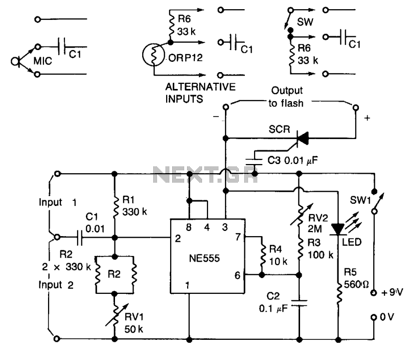
A negative pulse at the input is fed through capacitor C1 to the input pin (2) of the integrated circuit (IC). Pin 2 is maintained slightly above its triggering voltage of 1/3 Vcc by a voltage divider consisting of...
P1 47K logarithmic potentiometer; P2, P3 47K linear potentiometers; R1, R3, R5 4.7K 1/4W resistors; R2 22K 1/4W resistor; R4 1M 1/4W resistor; R6 1.8K 1/4W resistor; R7 560Ω 1/4W resistor; C1, C4, C5, C7 10 µF 63V electrolytic...
The following circuit illustrates a Dancing LEDs electronic circuit diagram. This circuit is based on the LM358 integrated circuit. Features: IC1A amplifies the signal. The Dancing LEDs circuit utilizes the LM358 operational amplifier to create a visually appealing light display....

The Switchgate is a simple dual gate circuit based on a 556 timer configured in monostable mode, featuring a trigger input that activates two switches. The outputs of the monostables are also available individually. Recent research has led to...
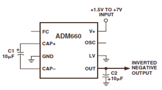
The ADM660 is a charge-pump voltage converter that can either invert the input supply voltage or double it. The schematic below depicts the ADM660 Voltage Inverter Circuit Configuration Diagram. This inverting schematic is ideal for generating a negative rail...