
Dual Fan Controller

The circuit utilizes an Atmel ATtiny45 or ATMega168 microcontroller to monitor the temperature via a thermistor, specifically the BC1482 model. The thermistor's resistance varies with temperature, allowing the microcontroller to determine the current temperature by measuring this resistance. The microcontroller is programmed to activate two fans when the temperature exceeds a predefined threshold, ensuring effective cooling of the PC.
The thermistor is connected in a voltage divider configuration with a fixed resistor. The output voltage from the divider is fed into one of the analog input pins of the microcontroller. The microcontroller reads this voltage and converts it into a temperature value using a predefined conversion table that links resistance values to Fahrenheit temperatures. This conversion table is essential for accurately interpreting the thermistor readings.
The fans are connected to the microcontroller via a relay or a transistor switch, allowing the microcontroller to control their operation based on the temperature readings. The choice of using two fans provides redundancy and enhances airflow, which is particularly important in the confined space of a kitchen cabinet.
In summary, this circuit effectively combines temperature sensing with fan control to maintain optimal operating conditions for a PC in a potentially warm environment, such as a kitchen. The use of an Atmel microcontroller allows for flexible programming and integration of additional features, such as adjustable temperature thresholds or fan speed control.Describes reading a thermistor using an Atmel ATtiny45 or ATMega168 microcontroller to drive two fans to cool a PC installed in a kitchen cabinet. Include a table for converting the BC1482 resistance to Fahrenheit.. 🔗 External reference
Related Circuits
Using a switch to power up your microcontroller projects may not be a good idea if you need to "wake" the PIC during some events. For example: A metal detector sends a pulse indicating a car is ready to...

The following circuit diagram of a dual voltage power supply can be used for miscellaneous applications. It requires a few components to build. The most important components of this circuit are regulators: 1: (AN) 7812 and 2: (AN) 7912....
This circuit can control a small DC motor, like the one in a tape recorder. When both the points A & B are "HIGH" Q1 and Q2 are in saturation. Hence the bases of Q3 to Q6 are grounded....
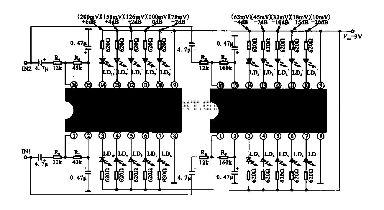
The circuit consists of dual drive integrated circuits (ICs) utilized in a 10 LED level meter configuration. The schematic features two TLM8101 driver ICs, which can be employed as alternatives. The 10 LED level meter circuit is designed to provide...
In this circuit, the 7815 regulates the positive supply, and the 7915 regulates the negative supply. The transformer should have a primary rating of 240/220 volts for Europe, or 120 volts for North America. The centre tapped secondary coil...
It was discovered through experience why the 6V EQ-5 hand controller should not be connected to 12V by mistake. It only took about half a second to damage the hand controller. Upon inspection, it became clear that the large...