
Dual Input-Combining Stereo Line Amplifier

The circuit is designed to facilitate the merging of two independent line-level stereo signals into a single output while preserving the stereo characteristics. This process is essential in applications where multiple audio sources need to be managed without the complexity of manually switching between them.
The core of the circuit typically involves operational amplifiers configured as summing amplifiers. Each line-level input signal is fed into the non-inverting terminals of the op-amps, which are configured to sum the signals. The output from each op-amp represents the combined left (L) and right (R) channels.
To ensure optimal performance, resistors are used to set the gain of the op-amps and to match the impedance of the input signals. This prevents signal degradation and maintains audio quality. Additionally, capacitors may be included in the design to filter out any unwanted noise and to stabilize the frequency response of the circuit.
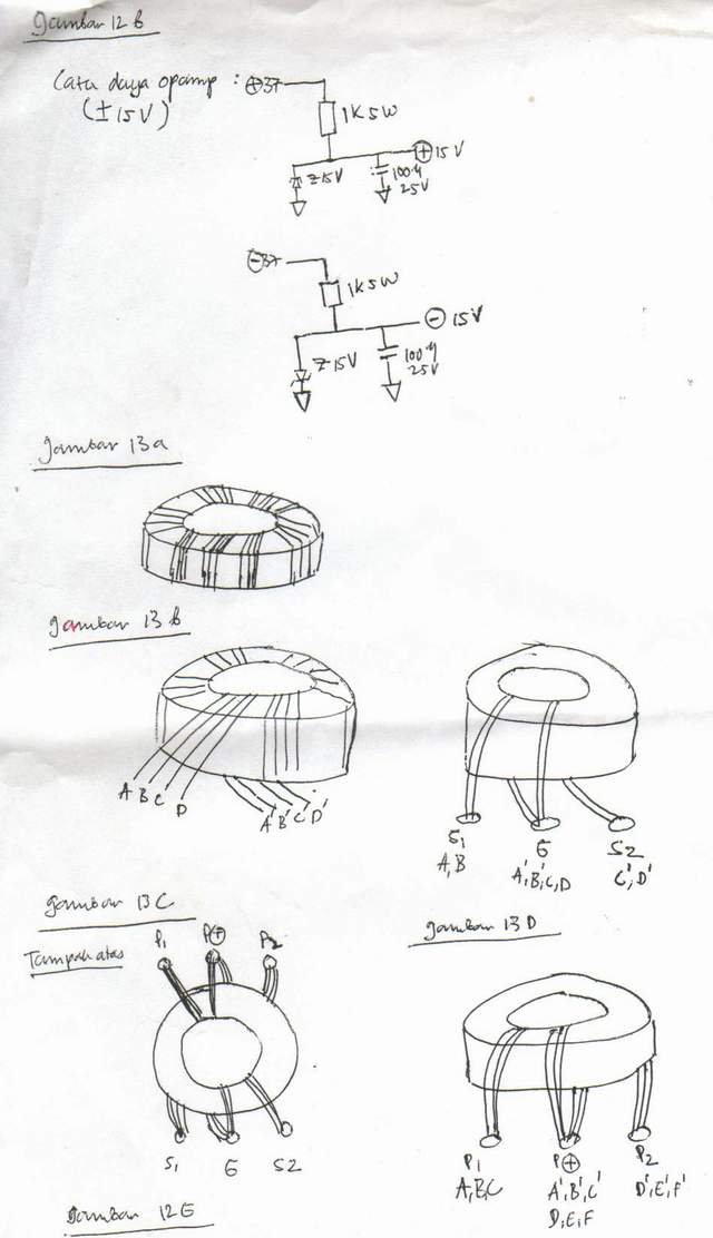
The circuit should also incorporate a power supply section to provide the necessary voltage levels for the op-amps. This is typically achieved using a dual power supply configuration, providing both positive and negative voltages to ensure that the op-amps can process the full range of audio signals.
In summary, this circuit effectively combines two line-level stereo inputs into a single output while maintaining audio fidelity, making it an invaluable component in audio mixing and signal routing applications.This circuit takes two separate line-level stereo (L & R) signals and combines them into one stereo (L & R) output, thus avoiding the need to switch betwe.. 🔗 External reference
Related Circuits
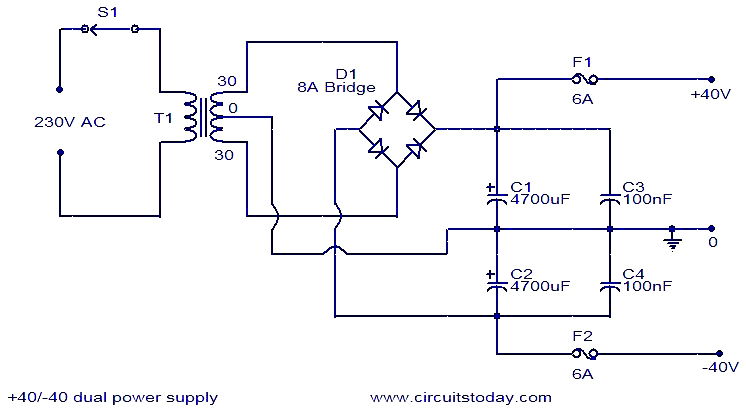
This 40V dual power supply circuit was designed to power a 150 Watt amplifier circuit. The transformer T1 steps down the mains voltage, while bridge D1 performs rectification. Capacitors C1 and C2 act as filters, and C3 and C4...
Utilizing an analog audio line delay, it is possible to virtually adjust the size of a room. By simply turning a knob on the audio equipment, one can modify the perceived room size. The circuit described herein facilitates this...
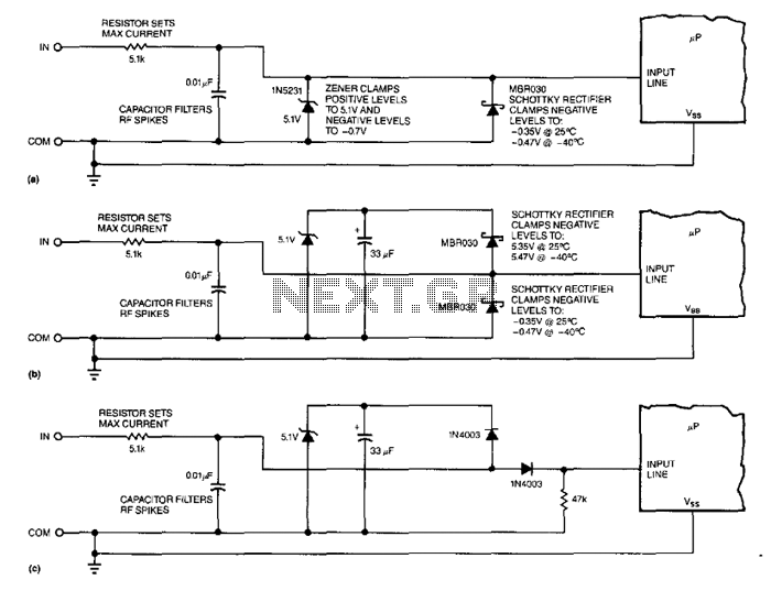
A 5.1-V zener diode is utilized to clamp positive-going transients, while a Schottky rectifier is employed to clamp negative-going transients. The Schottky rectifier, however, experiences issues at both extremes of the temperature range. At 125°C (257°F), its leakage current...
This article is intended for individuals interested in constructing their own car amplifier. The fundamental calculations involved will be discussed below. Understanding these concepts will enable the construction of a car amplifier independently. The complexity of designing a car...
While I would have liked a 4 channel chip with about 20 Watt per channel, the local parts store didn't have any yet, so I opted for two TA8215AH stereo chips, selected by their low price in this particular...
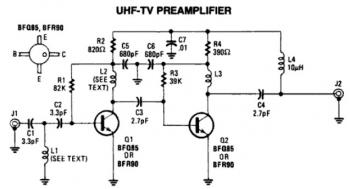
This is a low-cost, antenna-mounted UHF TV pre-amplifier circuit that can provide more than 25 dB of gain. The first stage of the pre-amplifier is biased for optimum gain. L1 and L2 are strip line equivalents with a length...