
I/O Line Protectors

The described circuit utilizes a combination of a zener diode and Schottky rectifier to manage voltage transients effectively. The 5.1-V zener diode serves as a voltage clamp for positive transients, ensuring that any voltage exceeding this threshold is diverted away from sensitive components. This is crucial in protecting integrated circuits from overvoltage conditions that could lead to damage or erroneous operation.
In contrast, the Schottky rectifier is tasked with handling negative transients. However, it is important to note that the performance of the Schottky rectifier can degrade under extreme temperature conditions. At elevated temperatures, particularly around 125°C, the leakage current can become significant, potentially affecting circuit performance, especially when high-value resistors (e.g., 100 kΩ) are used in the input stage. This leakage could lead to unintended biasing of the circuit, resulting in malfunction.
Conversely, at low temperatures, the forward voltage drop of the Schottky rectifier increases, approaching critical limits for HCMOS inputs. This behavior necessitates careful consideration when designing circuits intended to operate across wide temperature ranges, as it could lead to unreliable operation or damage to the input pins of integrated circuits.
The alternative configuration using standard silicon rectifiers offers a robust solution to the issues presented by the Schottky rectifier. By employing two silicon rectifiers, one serves to isolate the input from negative voltage spikes, while the other, in conjunction with the zener diode, manages positive transients. This configuration not only enhances reliability across temperature variations but also provides a more predictable voltage response, making it suitable for applications where circuit integrity is paramount. The use of silicon rectifiers may introduce a higher forward voltage drop compared to Schottky devices, but the trade-off is often justified by improved performance under varying environmental conditions. A 5.1-V zener diode clamps positive-going transients, and a Schottky rectifier clamps negative-going transients. Th e Schottky rectifier has problems at both ends of the temperature scale. At 125°C (257°F), its leakage current can reach 50 when the input line is at 5 V. This leakage is not a big deal unless the input resistor has a value of 100 kfi or more. More troubling, at temperatures below -40°C (-40°F), the Schottky rectifier"s forward voltage rises to about 0.47 V, which is perilously close to the -0.50-V max spec that most HCMOS-type /iP"s inputs can tolerate. The third circuit, Fig. 20-3(c), uses two regular silicon rectifiers. One rectifier is connected in series with the input line, thereby isolating the " inputs from negative-going voltage spikes.
The other rectifier is in series with a 5.1-V zener, which clamps positive-going transients.
Related Circuits
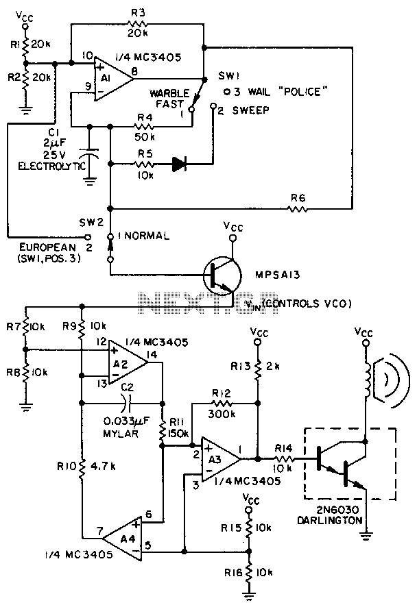
A low-frequency op-amp oscillator and a voltage-controlled oscillator (VCO), both configured using a single MC3405 dual op-amp and dual comparator, are the primary components in a siren circuit capable of producing various warbles and wails, or functioning as an...

The Bug-Eyed Eggliner project involves creating a whimsical animated figure with large, illuminated, and movable eyes. The project utilizes a combination of wooden balls for the eyes, a PICAXE microcontroller for control, and a servo mechanism to achieve eye...
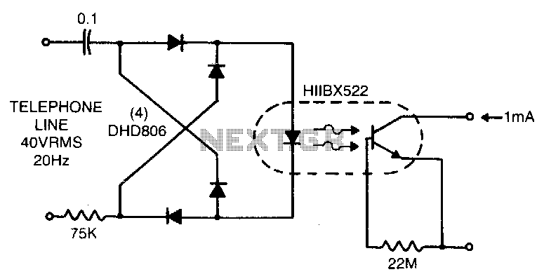
Low line current loading is provided by the H11BX522 photodarlington optocoupler, which delivers a 1 mA output from a 0.5 mA input. The H11BX522 is a photodarlington optocoupler that is designed to provide electrical isolation between its input and output...
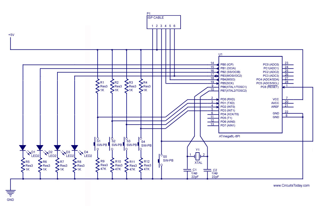
How to handle digital input/output (I/O) in AVR microcontrollers is explained using basic programs and circuits to illuminate an LED, generate a stepper motor sequence, read a push-button switch, and implement key debouncing. The handling of digital I/O in AVR...
It is widely recognized that power-saving regulations necessitate very low power consumption during standby conditions for all equipment continuously connected to mains power. In the standard version of the power supply, standby power consumption is approximately 9.0 W for...
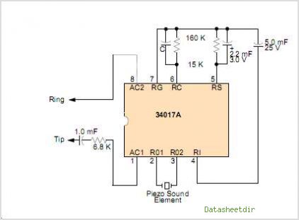
Many a times one needs an extra telephone ringer in an adjoining room to know if there is an incoming call. For example, if the telephone is installed in the drawing room you may need an extra ringer in...