
Dual-Motor SIP&PUFF Controlled Kayak System

The provided description indicates a focus on the efficiency of system installation at a launch site, as showcased in a YouTube video. In an electronic schematic context, this could refer to the configuration of various components and subsystems necessary for a launch operation.
A comprehensive setup at a launch site typically involves numerous electronic systems, including telemetry, communication, power distribution, and control systems. Each subsystem must be integrated seamlessly to ensure reliable operation during critical phases of the launch.
The telemetry system is responsible for collecting data from various sensors and transmitting it to ground control. This includes parameters such as temperature, pressure, and structural integrity of the launch vehicle. Communication systems enable real-time interaction between the launch team and the vehicle, ensuring that commands can be sent and data received without delay.
Power distribution is crucial, as it involves distributing electrical power from the main source to various subsystems, ensuring that each component receives the necessary voltage and current. This often includes the use of power management ICs, voltage regulators, and backup power systems to maintain functionality in case of primary power failure.
Control systems encompass the software and hardware necessary to manage the launch sequence, including ignition, thrust vector control, and payload deployment. These systems rely on microcontrollers or FPGAs programmed to execute specific tasks based on sensor inputs and predefined algorithms.
In conclusion, the quick setup of such a comprehensive electronic system at a launch site is essential for the success of the operation, highlighting the importance of meticulous planning, robust design, and efficient integration of all electronic components.Jumping ahead just a little The YouTube video below illustrates how quickly and easily the system is set up at the launch site My to.. 🔗 External reference
Related Circuits
The control voltage is fed into the first half of a 1458 op-amp, this stage inverts the signal and sets the offset and gain for the right channel gain control circuit. This signal is then fed into the second...
This Project is made up with AT89C2051 and the RTC DS1307. It has a large Seven segment display. The standard remote control is used to change the Time. More: Procedure to enter the Time 1. Press power button on...
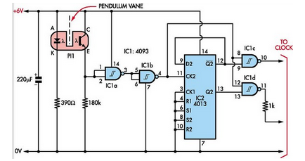
Here is how to build a pendulum-controlled clock that can be made very accurate. Retro? Yes, but it is an interesting project nonetheless. You will need a specific set of components. A pendulum-controlled clock is a mechanical timekeeping device that...
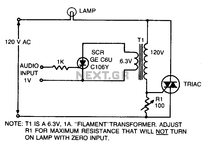
This is an on-off control with an isolated, low voltage input. The switching action occurs rapidly compared to the response time of the lamp and the human eye, resulting in an effect with audio input that resembles a proportional...
This homemade GSM car security system features a straightforward circuit design that effectively operates as a GSM car security system. The homemade GSM car security system employs a simple yet effective circuit design that integrates a GSM module, microcontroller, and...
The color wheel and motor control are customizable. This system utilizes field-sequential color rather than the "compatible color" introduced later. Following the wiring modifications, further details about the color wheel will be provided. Without the wheel, CBS shows can...