
TV to receive CBS-System Color (1951)
")
The CBS color television system represents a significant advancement in broadcast technology, utilizing a unique approach to color reproduction through field-sequential color. This method requires precise timing and synchronization of the oscillators, which are crucial for the accurate display of images. The increased frequencies in the CBS system are essential for achieving the desired color fidelity and image clarity, as they allow for faster scanning rates, resulting in smoother transitions and reduced flicker during color display.
The incorporation of a multipoint switch provides flexibility in operation, enabling users to easily toggle between monochrome and color viewing. This design consideration enhances user experience, particularly for those who may prefer to watch certain programs in black-and-white. The addition of fixed resistors and potentiometers further refines the control over picture size, ensuring that the user does not have to repeatedly adjust settings when switching modes. This is particularly advantageous in environments where quick adjustments are necessary, such as live broadcasts or dynamic content.
The use of triodes in the oscillator circuits exemplifies a traditional approach to signal generation in television technology, where reliability and performance are paramount. The integration of these components, along with the specified resistor values, ensures that the oscillators can maintain stable operation under varying conditions, providing consistent performance across different television models.
In summary, the modifications outlined for the CBS color television system not only enhance color performance but also streamline user interaction with the device, making it a noteworthy advancement in television technology during its time. The detailed wiring changes and component specifications serve as a guide for technicians and engineers aiming to implement or understand this innovative system.The color wheel and motor control are up to you. Yes, this is field-sequential color, not the "compatible color" that came along a few years later. After we detail the wiring changes, we`ll tell you more about the wheel. Anyway, even without the wheel, you`ll be able to see CBS shows in black-and-white. The basics. All TV sets have time bases. Inside each TV timebase is a horizontal and a vertical oscillator. These oscillators output frequencies that control picture scanning. Picture scanning is what forms pictures on the screen. In the CBS color system, both oscillators operate at higher frequencies than in the regular American TV system (NTSC). CBS frequencies. For the horizontal frequency, the CBS system uses 29, 160 instead of 15, 750 Hz. For the vertical frequency, the CBS system uses 144 instead of 60 Hz. Fixed resistors in series with the TV`s front-panel hold controls set these timebase frequencies. You`ll add a multipoint switch that selects the monochrome or color frequency. The switch connects either the old horizontal and vertical resistors or new ones. The resistors that you need to add are all fixed resistors. The new parts connect in series with the horizontal and vertical hold potentiometers. A typical value for the new resistors is 20K. In some models, a 10K resistor does the trick. Extra size controls. The switch also selects a second horizontal width and vertical height potentiometer. These parts are identical to those in a stock set. The new pots keep the color picture the same size as the monochrome picture. These pots are definitely worthwhile! Without them, whenever you switch to color, you must increase picture size. All the size adjustments could get to be a major pain in the neck. With the second set of pots, you adjust the color picture size just once. And then you`re done. The table below summarizes the wiring changes for several popular TV models. The changes allow your set`s horizontal and vertical oscillators to operate at higher frequencies. If you know your thumb from a soldering iron, you can`t go wrong. Peter Goldmark and his CBS engineers worked everything out. About the table. The table below lists five TVs with similar circuits. All these sets use a 12SN7 or 6SN7 tube for the horizontal and vertical oscillator. Another common point among the sets is that they use electrostatic deflection. The sets also have scope-like power supplies. That is, the high voltage doesn`t derive from a flyback power source. The added fixed resistors control oscillator frequencies. Each resistor usually runs between ground and the grid of a triode. The triode could be part of a multivibrator. Or it could be a blocking oscillator. In the table, the (B&W) value indicates the stock resistor in the monochrome circuit. The (C) value is the resistor value that you must add. 🔗 External reference
Related Circuits

This project will explain how you can build a receiver for 35MHz. The receiver is based on the FM receiver circuit MC3371, and the frequency is PLL controlled with LMX2306 circuit. In this project, a radio receiver for RC...
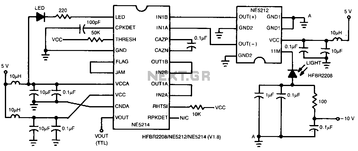
This two-chip receiver, designed for low-cost fiber optic applications at 100-M baud (50 MHz), features a minimal external component count. The receiver consists of pre-amplifier and post-amplifier integrated circuits (ICs) for enhanced stability. The preamplifier IC is characterized by...
40-meter Direct Conversion Receiver. Using the circuit of a 40-meter band direct-conversion receiver described here, one can listen to amateur radio QSO signals in both CW and SSB modes. The 40-meter direct conversion receiver is designed to facilitate the reception...
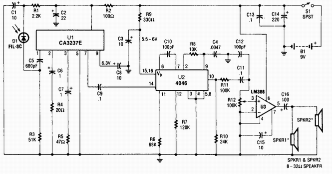
A photodiode D1 feeds a high-gain infrared (IR) remote control preamplifier IC, specifically a CA3237E. U2 is a phase-locked loop (PLL) frequency modulation (FM) detector tuned to approximately 100 kHz. The output from the detector is amplified by U3,...
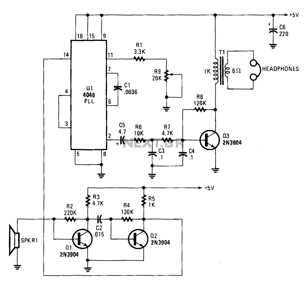
The 4046 PLL is utilized as the core component of a tunable ultrasonic receiver designed for detecting inaudible ultrasonic sounds. This receiver can also function in conjunction with a simple ultrasonic generator to transmit and receive Morse code. The...
In the image above, Oscium's iMSO-104 oscilloscope is measuring the output waveform of an infrared receiver (IR Rx). The iPad and iMSO serve as the oscilloscope to measure the receiver's output signal as the alignment between the transmitter and...