
Voltage Controlled Panner

The described circuit utilizes a dual operational amplifier (op-amp) configuration, specifically the LM1458, to create a voltage-controlled audio panner. The first half of the op-amp inverts the input control voltage, which is crucial for establishing the gain characteristics of the right channel. The output from this stage serves as the input for the second half of the op-amp, which inverts the signal once more to derive the gain control for the left channel. This dual inversion process ensures that the gain adjustments for both channels can be effectively controlled by a single control voltage input.
The circuit includes a 10K trimmer potentiometer, which allows for fine-tuning of the left channel gain. By setting this trimmer correctly, both channels can achieve equal gain when the control voltage is set to 5V, thus ensuring balanced audio output. The audio signal path is designed to be identical for both channels, although only one channel is depicted in the schematic for simplicity.
In terms of gain control, the circuit employs a pair of 2N3904 transistors configured as a differential pair. This arrangement is essential for providing voltage-controlled gain, as the matched transistors respond uniformly to changes in the control voltage. It is important to ensure that the two transistors are closely matched to maintain consistent performance across the audio spectrum.
The output of each gain control stage is routed to an NE5532 op-amp, which operates as a low-noise differential amplifier. This stage is critical for preserving the integrity of the audio signal, minimizing noise and distortion before the final output.
The circuit's versatility is highlighted by its potential applications in audio effects and as a plug-in module for voltage-controlled synthesizers. The design features a single control voltage input, one audio input, and two audio outputs, which allows for flexible signal routing. The control voltage can vary continuously between 0V and 10V, enabling precise panning of the audio signal: 0V directs the output fully to the left, 5V centers the output, and 10V directs it fully to the right.
Furthermore, there is an opportunity to enhance the circuit by substituting the existing voltage-controlled amplifier (VCA) stages with an LM13700 dual transconductance amplifier IC. This modification could provide additional performance benefits and should be explored further by consulting the LM13700 application notes for implementation details.The control voltage is fed into the first half of a 1458 op-amp, this stage inverts the signal and sets the offset and gain for the right channel gain control circuit. This signal is then fed into the second half of the 1458 op-amp which inverts the voltage again and generates the signal for the left gain control circuit.
The 10K trimmer adjusts the Left channel gain, set it for equal gain from both channels with 5V on the control input. Each audio stage is identical, only one is shown in the schematic. The pair of 2N3904 transistors form a differential pair that provides voltage controlled gain. The two transistors should be matched, see the note on the schematic. Each gain control stage is fed into an NE5532 low noise audio op-amp that is wired as a differential amplifier.
This circuit is useful for audio effects and may be used as a standard plug-in module for voltage controlled synthesizers. The circuit has one control voltage input, one audio input and two audio outputs. The control voltage input can be supplied with a continuously variable voltage from 0V to 10V, 0V pans the signal to the left output, 5V pans the signal to the center, and 10V pans the signal to the right output.
Taking the circuit further, it should be possible to replace the two VCA circuits in this panner with a National Semiconductor LM13700 dual transconductance amplifier IC wired as two voltage controlled amplifiers. See the LM13700 applications notes for details. 🔗 External reference
Related Circuits
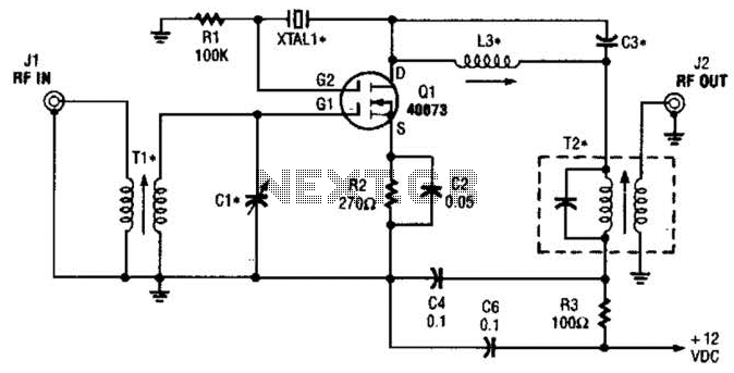
The second gate (G2) of a MOSFET can be utilized to integrate a crystal oscillator within the same stage as a frequency mixer. While this technique is common in tube technology, it is rarely implemented in dual-gate MOSFET circuits....
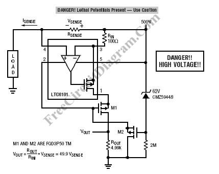
High voltage current sensing and monitoring can be designed using the LTC6101 operational amplifier. The current sensing circuit outlined is capable of measuring electrical current. The LTC6101 is a precision current sense amplifier designed to operate in high voltage environments,...
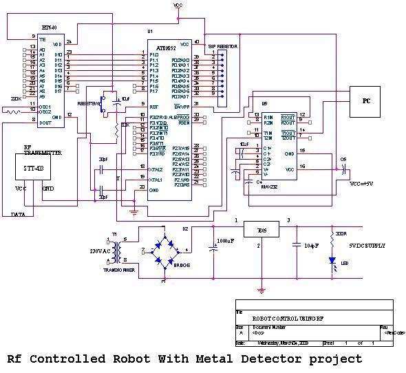
An embedded C-based RF-controlled robot equipped with a metal detector, along with wireless image and voice transmission capabilities. This project report is intended for electronics and communication engineering students. The project involves the design and implementation of an RF-controlled robot...
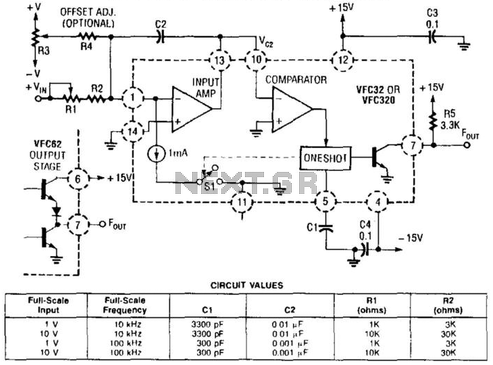
This voltage-to-frequency converter utilizes a Burr-Brown VFC 32 integrated circuit (IC) and requires minimal components. The circuit values are illustrated in the accompanying figure. This charge-balanced voltage-to-frequency (V/F) converter employs either a VFC32 or a VFC320 IC. The positive...
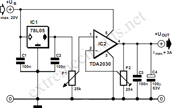
This adjustable voltage regulator is created by combining a standard 78L05 with an integrated audio amplifier of the type TDA2030, resulting in an adjustable voltage regulator. The circuit utilizes the 78L05 voltage regulator, which is a low dropout linear regulator...
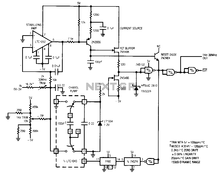
The circuit features a 1 Hz to 30 MHz output with a dynamic range of 150 dB, designed for a 0 to 5 V input. It exhibits a linearity of 0.08% across its entire 71/3 decade range, with a...