
Dual Polarity Power Supply

This dual polarity power supply circuit is designed to provide a stable voltage output ranging from 0 to 15 volts, making it versatile for various electronic applications. The circuit is built around two voltage regulators, denoted as U1 and U2, which are responsible for generating the positive and negative voltage rails. The use of operational amplifiers in circuits often necessitates a dual supply, and this design effectively meets that requirement with ease of assembly and minimal component count.
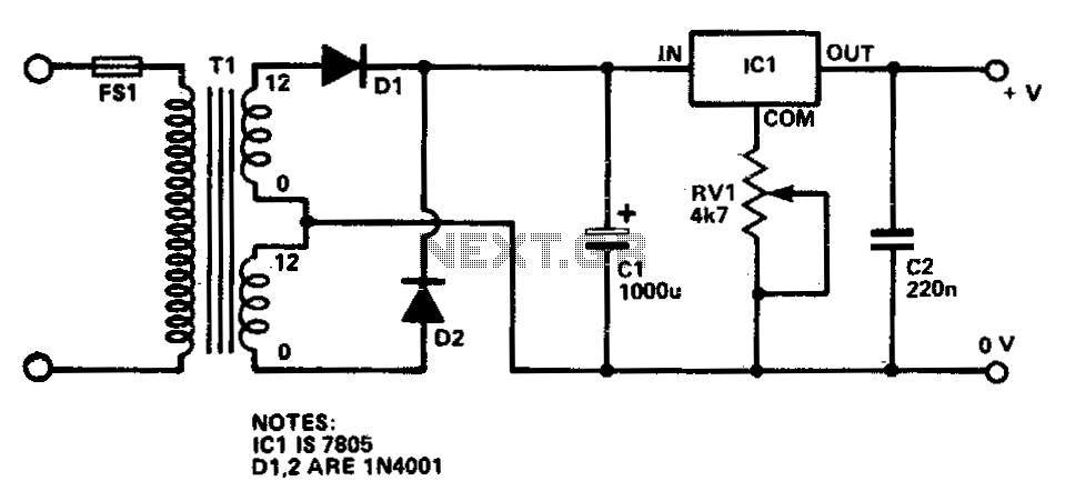
The voltage regulators selected for this circuit typically have a minimum output voltage of ±1.2V. In scenarios where lower voltage outputs are needed, the addition of two 1N4003 diodes in series with the output of the regulators is recommended. Each diode introduces a forward voltage drop of approximately 0.6V, which allows the output voltage to be adjusted down to 0 volts. It is important to note that incorporating these diodes will also reduce the maximum output voltage of the power supply by a total of 1.2V, which must be considered in the design phase.
The circuit layout should include appropriate filtering capacitors at the input and output of the voltage regulators to ensure stable operation and minimize ripple voltage. Additionally, heat sinks may be required depending on the load current to maintain the thermal stability of the regulators. Proper attention to the layout and grounding techniques will enhance performance and reliability, making this dual polarity power supply an excellent choice for experimental and prototyping environments.This dual polarity power supply is easy to build, requires few parts, and is adjustable from 0-15 volts. It is great for powering op amp circuits, as well as other circuits that require a dual supply voltage.
4. U1 and U2 can only go down to a minimum of +-1. 2V. If you need to go lower, you can add two 1N4003 diodes in series with the output of th e regulator. The diodes drop about 0. 6V each, which will allow the supply to go to 0. Note that this will also decrease your maximum output voltage by 1. 2V. (Thanks to Steve Horvath, horvaths@techcomnet. com for the suggestion). 🔗 External reference
Related Circuits
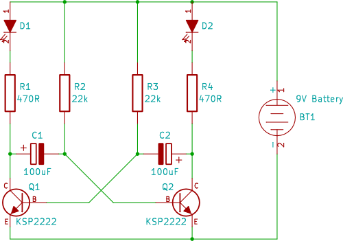
A two-transistor circuit that alternately flashes two LEDs on and off. This tutorial demonstrates how beginners in electronics can build this simple circuit on a breadboard. This circuit utilizes two NPN transistors configured in a flip-flop arrangement, which allows for...
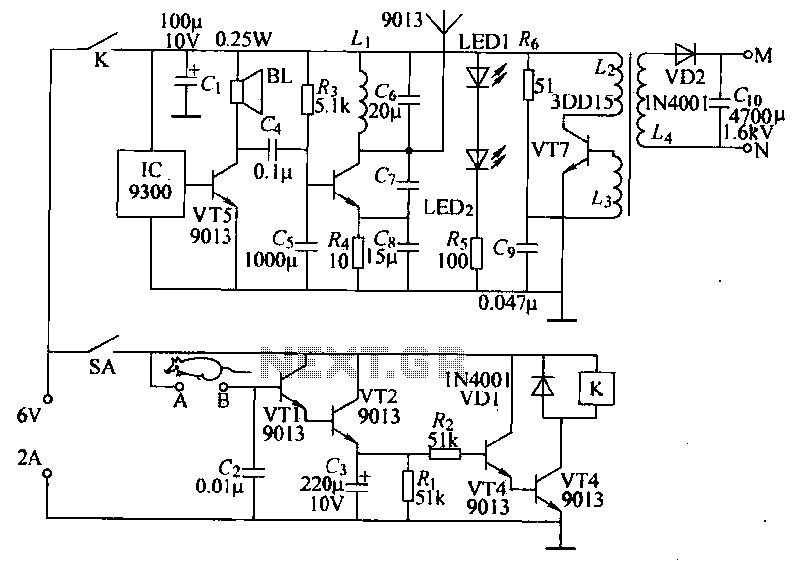
Power-saving electronic mousetrap. This example describes the minimal power consumption, which only occurs when a mouse enters the control zone during foraging activities. After a 30-second delay, the system enters a wait state, making it suitable for outdoor use....
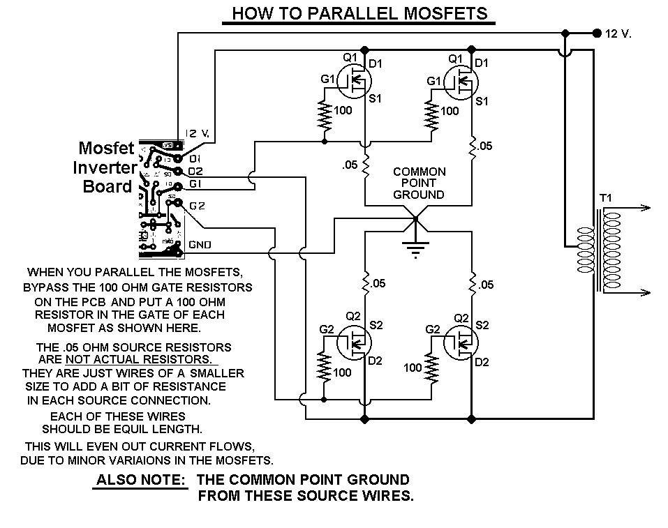
This 1000-watt power inverter circuit diagram utilizes the MOSFET RF50N06. To achieve higher power output, additional MOSFETs can be connected in parallel with the RF50N06. These MOSFETs are rated for 60 volts and 50 amps. It is essential to...
This regulated power supply is adjustable between a few volts and 15V using P1, while P2 is used to set the upper limit at 15.0V. The value of R6 is calculated as 0.7V divided by Imax, where Imax represents...
This circuit provides a regulated output voltage ranging from 5 V to 15 V DC, which can be adjusted using a preset resistor. The current output can reach up to approximately 350 mA. An integrated circuit is utilized to...
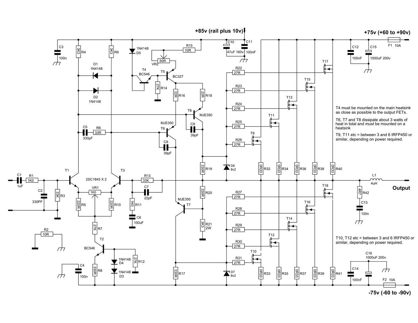
This circuit is a Power Amplifier designed to deliver an output power exceeding 600 Watts for speakers with an impedance of 4 Ohms. The high-power amplifier circuit utilizes six n-channel MOSFETs in the output stage, which alone provides approximately...