
Electronic mousetrap power-saving circuit

The electronic mousetrap employs a sophisticated control circuit that minimizes power usage while maintaining effective rodent detection and elimination capabilities. The circuit is designed around several key components that work in conjunction to ensure reliable operation. The control circuit, consisting of transistors VT1 to VT4, is responsible for monitoring the control zone. These transistors are configured to form a sensitive detection mechanism that responds to the presence of a mouse. When the mouse enters the designated area, it completes an electrical path between electrodes A and B, which activates the control circuit.
The alarm system is critical for alerting nearby personnel. It utilizes an integrated circuit (IC) paired with a transistor (VT5) to drive a speaker that emits an audible alarm. This feature ensures that custodial staff are notified promptly when a mouse is detected, allowing for timely intervention.
For remote monitoring, the transmitter circuit, led by VT6, operates within the FM frequency range of 88 to 108 MHz. This design allows for effective communication over distances greater than 1 km, enabling staff to monitor the mousetrap's status without being physically present.
The high-voltage generation circuit, which includes VT7 and VD2, is designed to deliver lethal voltage levels to eliminate any mice that enter the control area. This circuit is activated only when the control circuit confirms the presence of a mouse, ensuring that the high-voltage system remains inactive during idle periods to conserve energy.
The inclusion of a manual switch (SA) allows for easy activation of the system, providing flexibility in deployment. The design incorporates a delay mechanism of approximately 30 seconds after the mouse leaves the area, which prevents unnecessary activation of the high-voltage circuit and helps to extend the lifespan of the components.
Overall, the power-saving electronic mousetrap is a well-engineered solution that combines efficiency with effectiveness in rodent control, making it a viable option for outdoor environments where traditional traps may be less practical.Power-saving electronic mousetrap This example describes the usual minimal power consumption, only when the mouse enters the control zone when foraging work, and then after the 30s delay fork into the wait state, it is suitable for outdoor use mousetrap. (1) Working principle of 23-11 knots electrical circuit diagram of the electronic mousetrap. VT1 ~ VT4 composed of a control circuit and related components, and its role is to enter the notification whether the mouse control system area, and alarm and control voltage generating electrical power to the road.
IC, VT5 etc. alarm circuit, when a rat entered the control area, IC alarm signal by pushing VT5 speaker microphone BL sound. VT6 and the peripheral element pieces composed transmitter operating frequency 88 ~ 108MHz, launch distance of lkm above, in order to implement remote monitoring.
VT7, T, etc. VD2 voltage generating circuit, the output of several hundred to several thousand volts pressure, to kill the mice enter controlled areas. When the manual switch SA is closed, the power supply to the control circuit power, then VTI-VT4 are closed, following the electrical alarm and t K is not energized high voltage circuit does not work.
When the mouse enters that triggers when the equivalent of between A, B electrodes, a resistor. VT1 ~ VT4- are conduction, the relay K pull its contact K is closed, the alarm and high voltage generating power supply circuit is turned on. At the same time, the power supply to the cz charged by VT1, VT2, so that when the mice after departure triggers a relay delay about 30s closed.
VT7 avoid prolonged work impaired, but also reduce the power consumption of useless. Alarm IC sent all the way through the speaker BL charcoal sound. Another way was prepared by a high-frequency oscillator consisting of VT6, and emitted outside. At the same time, the light emitting diode LED1, LED2 light. Since then the mice frightened and fled into the high-voltage triggers a t Arab was killed. Upon receipt of an alarm signal in the distance custodial staff with FM radio, to the scene in time to clear the dead rats.
Related Circuits

This circuit illustrates a 2W RF amplifier based on the M/A-Com LF2810A MOSFET. The transistor is rated for 10 watts at 28 volts. The 2W RF amplifier circuit utilizing the M/A-Com LF2810A MOSFET is designed to amplify radio frequency signals...

This circuit for a laser door alarm operates on the principle of laser beam interruption. A low-cost laser pointer serves as the light source. When an object disrupts the laser beam, an alarm is triggered for a few seconds....

A narrowband linear amplifier circuit configured with the RF2320 operates within a frequency range of 1930 to 1990 MHz. The radio frequency (RF) signal is input from a distance of 6 feet and is amplified by an internal amplifier...

The FM transmitter circuit is built using a single MAX2606 chip. This simple FM transmitter connects a home entertainment system to a portable radio, allowing music to be played in one room and listened to in another, such as...
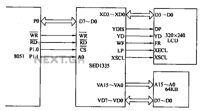
The MCS-51 series single-chip interface circuit 8051 is utilized to control the SED1335 35 dot matrix LCD display. This controller can manage up to a 640x256 dot matrix LCD display for both graphics and character representation, with the capability...

The hexFET can switch DC power to relays, motors, lamps, and various other devices. This configuration can also be utilized to switch resistors in and out of a circuit. R1, R2, and R3 represent resistive loads that can be...