
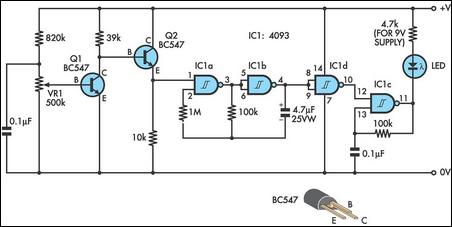
three level audio power indicator

The circuit operates by measuring the output voltage from the audio amplifier and converting this voltage into a corresponding power level indication. The design incorporates a voltage divider and a microcontroller or an analog display system to process the voltage levels.
To initiate the operation, the output signal from the amplifier is fed into a voltage divider network, which scales the voltage to a manageable level suitable for processing. This is crucial as the output voltage of audio amplifiers can exceed the input limits of most electronic components.
The microcontroller is programmed to interpret the scaled voltage levels and compare them against predefined thresholds that represent the three power levels. These thresholds can be set according to the specific requirements of the application, allowing for customization based on the amplifier's output characteristics.
Once the voltage is measured and processed, the microcontroller activates the corresponding indicator, which could be LEDs or an analog meter, to visually represent the power output. The use of three distinct levels allows users to quickly ascertain whether the amplifier is operating within the desired range, providing a straightforward visual cue that can enhance usability during operation.
This circuit is particularly beneficial in settings where audio performance is critical, such as live sound environments or studio applications, enabling users to monitor their equipment effectively and make necessary adjustments in real-time. The portable nature of the design makes it suitable for both stationary and mobile setups, ensuring versatility in various audio applications.This circuit is intended to indicate the power output level of any audio amplifier. It is simple, portable, and displays three power levels that can be set to any desired value.. 🔗 External reference
Related Circuits
This design integrates power-on and low-battery indication features, capable of operating with any battery voltage up to 15V. It has a very low current drain of 2mA or less and is cost-effective, priced under $3.50 with new components. When...
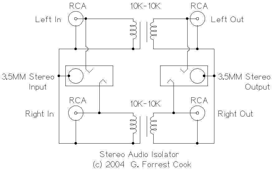
This circuit is useful for removing ground loop hum on a remote line level audio signal line. It can be used to connect a computer sound card to a stereo amplifier's line input. Other uses include tapping into a...
A mixer circuit is being developed. There is uncertainty regarding its functionality, and a request for verification has been made. In this schematic, resistors R1 and R2 are utilized. The mixer circuit typically combines two or more input signals into...
This project began with the exploration of arc starters that could be built at minimal cost using materials typically found in a tinker's workshop. Although it has been an enjoyable endeavor, the extensive collection of items in the basement...
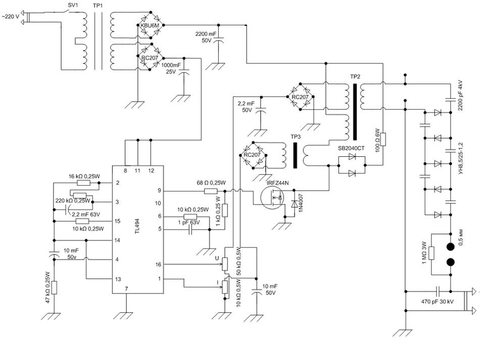
The schematic diagram is derived from the circuit of a High Voltage Power Supply utilizing the PWM IC TL494. This power supply requires a suitable alternating voltage source of 12 V / 800 mA. An alternating voltage is rectified...
This audio meter can be monitored using a small panel meter with a circuit constructed from discrete components. The audio level meter circuit exhibits a flat frequency response ranging from approximately 20Hz to over 50kHz. The input sensitivity is...