
Dual Regulated Power Supply 15v

The described circuit utilizes the 7815 and 7915 voltage regulators, which are linear voltage regulators designed to provide stable output voltages of +15V and -15V, respectively. These regulators are widely used in various electronic applications, including power supplies for operational amplifiers, analog circuits, and other devices requiring a dual power supply.
The transformer selected for this circuit plays a crucial role in stepping down the AC mains voltage to a suitable level for the regulators. The primary winding must be rated for either 240/220V for use in European countries or 120V for North American applications. A center-tapped secondary winding is essential, as it provides the necessary dual output voltages. The secondary coil should ideally be rated for approximately 18 volts, with a current capacity of at least 1 amp. This rating ensures that even under load, the output voltage remains stable after accounting for voltage drops across the regulators and any additional losses that may occur.
In terms of the circuit layout, the AC output from the transformer is connected to a full-wave bridge rectifier, which converts the AC voltage to pulsating DC. This pulsating DC is then filtered using a capacitor to smooth the output before it reaches the voltage regulators. The 7815 and 7915 regulators are connected to the filtered DC output, with appropriate input and output capacitors recommended by the manufacturers to ensure stability and transient response.
The output from the 7815 will provide a stable +15V supply, while the output from the 7915 will supply -15V. These outputs can be used to power various electronic components requiring dual supply voltages. The circuit can be further enhanced by adding additional filtering capacitors at the output of each regulator to improve the noise performance, especially in sensitive applications.
This power supply circuit is particularly suited for use as a small regulated bench power supply, providing a reliable source of dual voltage for testing and powering various electronic projects. Its simplicity and effectiveness make it a common choice among engineers and hobbyists alike.In this circuit, the 7815 regulatates the positive supply, and the 7915 regulates the negative supply. The transformer should have a primary rating of 240/220 volts for europe, or 120 volts for North America.
The centre tapped secondary coil should be rated about 18 volts at 1 amp or higher, allowing for losses in the regulator. An application for this type of circuit would be for a small regulated bench power supply. 🔗 External reference
Related Circuits
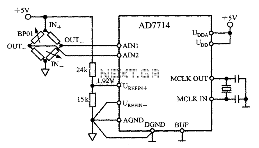
The AD7714 circuit consists of a pressure measurement system featuring the BP01 pressure sensor from Sensym. The BP01 is integrated into a bridge circuit, which produces a differential output voltage. When the sensor is subjected to its rated full-scale...
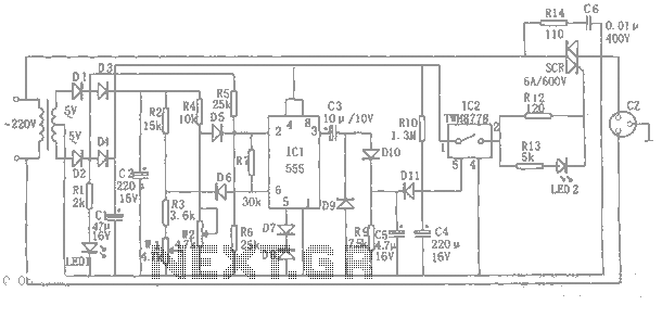
An automatic power protection circuit is presented. This protection includes a step-down rectifier circuit, an overvoltage and undervoltage detection circuit, and a delay switch control circuit. The step-down circuit is responsible for the entire rectifier circuit's DC voltage. The automatic...
A typical circuit for welding equipment is illustrated in the following circuit diagram. The turn-on delay can be accurately controlled with Potentiometer P2, allowing for effective discharge management. The welding equipment circuit typically incorporates several key components to ensure proper...

The objective is to vary two voltages, V1 and V2, by an equal percentage of their respective ranges (V1MAX - V1MIN and V2MAX - V2MIN), where V1MAX, V1MIN, V2MAX, and V2MIN are independent of one another. A common approach...
A column-parallel analog-to-digital converter (ADC) has been developed for integration with CMOS active pixel sensors (APS). The design objectives focused on simplicity, compactness, moderate speed (greater than 10 kHz), current input, and acceptable accuracy (6 bits). The ADC is...
Wireless power transfer is not a new concept; it has been discussed since Tesla's patent in 1900, titled "Apparatus for Transmission of Electrical Energy" (USPTO #649, 621). As the technology evolves, the range of potential applications will expand. For...