
Pulse-Train Triggering Circuit for Power Control

The welding equipment circuit typically incorporates several key components to ensure proper operation and safety during the welding process. The primary function of the circuit is to control the timing and delivery of power to the welding electrode, which is crucial for achieving optimal weld quality.
The circuit diagram will generally include a power supply unit that converts input voltage to the required operating voltage for the welding equipment. This power supply may feature voltage regulation components to maintain stable output under varying load conditions.
At the heart of the circuit is a control unit that may consist of a microcontroller or a timer IC, which governs the timing sequence of the welding operation. The turn-on delay, adjustable via Potentiometer P2, allows the operator to set the precise moment when the welding current is initiated. This feature is essential for applications requiring specific welding characteristics or for accommodating different materials.
Additionally, the circuit may include safety features such as fuses or circuit breakers to protect against overcurrent situations. The discharge path for the welding current will typically involve high-current-rated components such as transistors or relays, which must be selected based on the operational requirements of the welding process.
Signal conditioning components, such as resistors and capacitors, may be employed to filter out noise and stabilize the control signals. The output stage of the circuit is designed to handle the high power levels involved in welding, ensuring that the energy is delivered efficiently and effectively to the welding electrode.
Overall, the schematic representation of this welding equipment circuit provides a clear and comprehensive overview of the components and their interconnections, facilitating an understanding of how to implement and troubleshoot the system effectively.Typical circuit for welding equipment shown on the following circuit diagram. Turn on delay can be controlled accurately with Potentiometer P2. We can discharge. 🔗 External reference
Related Circuits
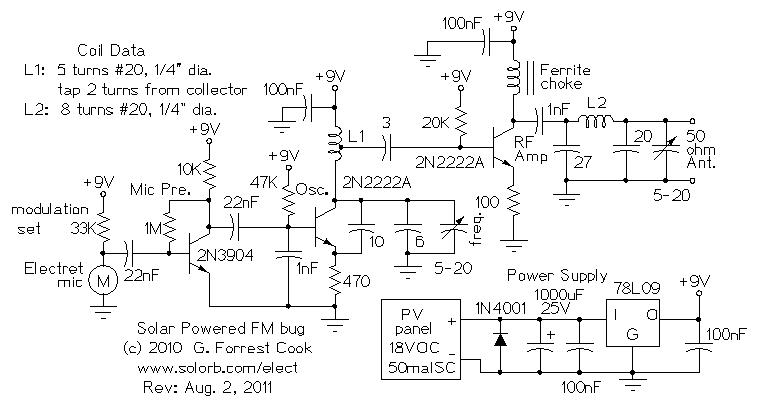
Numerous miniature FM transmitter bug circuits are available online; however, this particular design is distinctive as it operates entirely on solar power, eliminating the need for a battery. The transmitter will function as long as sunlight is incident on...
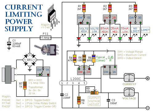
This is a 1-amp variable-voltage power supply unit (PSU) that can be adjusted from approximately 3V to 24V. It features a maximum output current limit, which is particularly useful when powering up a project for the first time or...
The economic fluorescent display circuit is illustrated in the figure. The primary component of this circuit is the 555 timer configured as a multivibrator. The oscillation frequency is determined by the components R1, R2, and C1, with a frequency...
The components available were utilized to create a long-range FM radio transmitter operating within the 88-108 MHz band, designed for playing music. The circuit includes a power section that rectifies mains voltage to provide a stable 12V DC for...
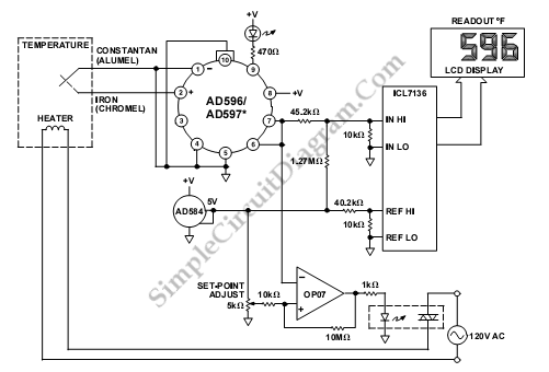
This is a temperature indication and control system utilizing the AD596/AD597. In this system, the AD596/AD597 functions as a closed-loop thermocouple signal conditioner. The temperature indication and control system based on the AD596/AD597 integrates a thermocouple sensor to measure temperature...
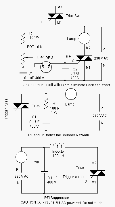
Advanced power control systems utilize electronic components such as thyristors for power switching, motor control, and other applications. These systems are involved in inverter design, lamp dimming, and speed control of motors. Triacs are the most commonly used semiconductor...