
Manpower sensing alarm circuit

The manpower inductive alarm circuit utilizes a sensing line to detect the presence of individuals within a specified range. The core component of the circuit is the NE555 timer IC, configured in a monostable mode. The sensing line, designated as L, is a length of wire that serves as the detection element. The optimal length of this wire is around 50 cm; lengths beyond this may lead to undesired triggering of the alarm system due to noise or interference.
When an individual approaches the sensing line within 15 cm, the proximity induces a detectable signal in the wire. This induced signal is fed into the NE555 timer's trigger input (pin 2). The NE555 timer is designed to respond to low-voltage signals due to its high input impedance, allowing it to react even to weak signals. Once triggered, the timer generates a pulse at its output (pin 3), which activates the connected speaker (BL), generating an audible alarm sound.
The circuit's sensitivity can be finely tuned by adjusting the resistor and capacitor values associated with the NE555 timer, which control the duration and characteristics of the output pulse. The alarm sound is designed to last for a brief period—approximately one second—before automatically silencing, ensuring that the system is efficient and does not cause prolonged disturbances.
This type of alarm circuit is particularly useful in security applications, where discreet and immediate alerts are necessary upon detecting unauthorized access. The simplicity of the circuit design allows for easy implementation and integration into various security systems, providing an effective solution for monitoring sensitive areas.As shown in manpower inductive alarm circuit, simple and practical, when a person's hand near the sensing line, the alarm will send out alarm sound, which is very suitable for the male electrical burglar alarm. Induction line L is a long lo ~ 50cm of wire, wire as if too long, it will cause the alarm from the alarm. When the staff proximity sensing line when L, will induce a signal in the L, the signal is applied to the time base circuit NE555 first feet and legs, and feet due feet high input impedance, even a weak induction signals 555 will work, the first feet strong signal to drive the speaker BL sound. The alarm sensitivity is high, the manpower from the flux lines at 15cm, silent alarm sound an alarm, continue 1 Meng and then disappears.
Related Circuits
A collection of guitar fuzz, preamp, and operational amplifier (op-amp) electronic circuits and schematics designed for various guitar effects and distortion effects. This compilation includes a diverse range of electronic circuits that cater to guitarists seeking to enhance their sound...

The multi-purpose signal generator circuit consists of integrated circuit oscillators and frequency dividers. It generates square waves ranging from high frequencies to sub-audio frequencies and also produces a frequency standard in the VHF range. The alternative oscillator section feeds...

This document discusses an Asynchronous 4-Bit Binary Up Counter, a circuit constructed from several J-K flip-flops connected in a cascade configuration to produce a four-bit counting sequence. An up counter is a digital counting circuit that increments its count...

This page contains various small circuits created over time. Some circuits are trivial, while others are more complex, but all are intended to be useful for a variety of projects. Most include both the schematics and the source (KiCad)...
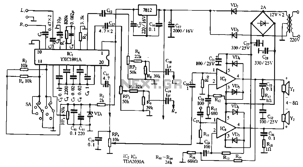
The ptPC1891A application circuit features a working state switch (SA) with a total of four options. It primarily utilizes ICs 11 and 12 to set different logical levels, as referenced in Table 5-12. The high level is denoted as...
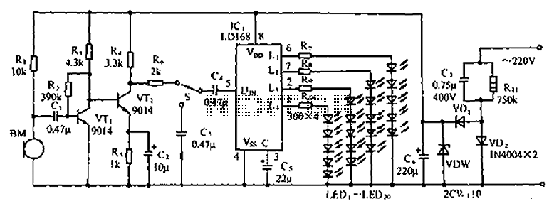
The circuit depicted in the figure involves the LD168, which functions as a sound level indicator for tape recorder speakers. It features four outputs capable of directly driving multiple light-emitting diodes. Additionally, the device can be activated by a...