
Error amplifier limitations in high-performance regulator applications

In modern power supply design, the trend towards higher switching frequencies necessitates the use of elevated loop crossover frequencies. This adjustment is crucial for accommodating the increasing demands of load transient response, which refers to the power supply's ability to adjust to rapid changes in load conditions. A higher crossover frequency allows the power supply to respond more swiftly to these transient events, thereby maintaining output voltage stability and performance.
The implications of these design choices extend to the selection and sizing of filter components. By increasing the crossover frequency, it is possible to minimize both the number and size of passive components such as inductors and capacitors. This reduction is particularly beneficial in applications where space and weight are critical factors, such as in portable electronics or compact power systems.
In voltage-mode control schemes, the role of the voltage loop error amplifier becomes increasingly significant. As the loop crossover frequency rises, the error amplifier must provide a greater compensating gain to ensure stability and adequate transient response. This requirement places additional demands on the design and performance of the error amplifier, necessitating careful consideration of its bandwidth, slew rate, and overall dynamic performance.
To achieve optimal performance in high-frequency power supply designs, engineers must balance the trade-offs between loop bandwidth, stability margins, and component selection. Advanced compensation techniques may be employed to enhance the performance of the voltage loop, ensuring that it can adequately respond to the rapid load changes while maintaining system stability. In conclusion, as power supply designs continue to evolve towards higher frequencies, the challenges associated with loop compensation and transient response will remain critical considerations for engineers in the field.As power supply switching frequencies increase, higher loop crossover frequencies are necessary to keep pace with the escalating load transient slew rate demands, and to reduce the number and size of filter components. For voltage-mode-controlled supplies, the voltage loop error amplifier must work harder to provide its compensating gain loop contribution.
.. 🔗 External reference
Related Circuits
There is no substitute for sheer power—low-efficiency speakers, outdoor sound systems, or perhaps the full dynamic range of a high-power amplifier. Whatever the requirement, this super power module should meet the needs. The amplifier can be divided into three...
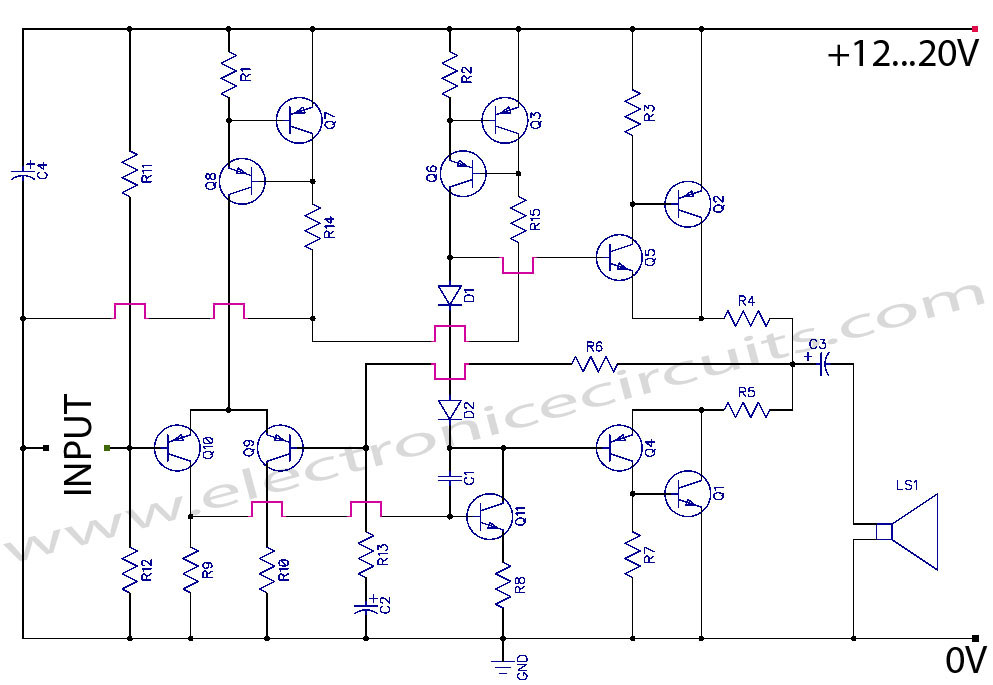
Discrete Class AB Transistor Audio Power Amplifier Circuit Diagram. This is a Class AB transistor power amplifier. It is a simple amplifier to... A Class AB transistor audio power amplifier is designed to provide high-quality amplification for audio signals while...
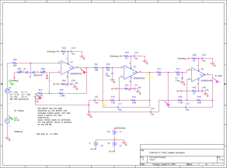
A bandwidth-limited amplifier shapes the waveform sampled by the 40 MHz high-speed pipeline Analog to Digital Converter (fast ADC, or fADC). It is well known that the shaping time is twice the time constant (peaking time) for each pole...
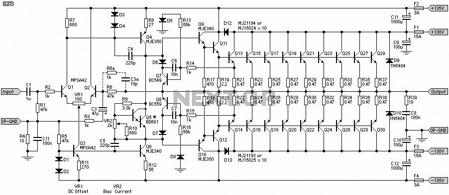
A 1500W power amplifier circuit design diagram created by Rod Elliott. The circuit utilizes 10 pairs of power transistors, specifically MJ15024 and MJ15025, or alternatively MJ21193 and MJ21194. The 1500W power amplifier circuit is designed for high-performance audio applications, providing...
This circuit is designed for use with inductive pick-up elements and dynamic microphones. Most soundcards feature a line input and a separate input for electret (condenser) microphones. To connect an inductive tape recorder head or a dynamic microphone, an...
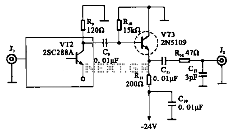
A high-frequency signal is displayed in the output amplifier. The circuit consists of a VI3 common collector amplifier (emitter follower) designed to enhance the child-band. It is a high-frequency amplifier (1-250 MHz) that increases the output voltage and boosts...