
Dual Tone Sounder Circuit

The oscillator frequencies (and consequently the tones they generate) can be modified by adjusting the values of R1 and C7 for the low-frequency oscillator, and R2 and C2 for the high-frequency oscillator. Reducing the values of these components will increase the frequency, while increasing their values will decrease the frequency. The outputs from the two oscillators are fed into separate amplifiers configured as emitter followers, which drive a single power transistor (Q3, an MJE3055). A 10- or 5-ohm resistor, R5, is utilized to limit the current flowing through the speaker and Q3 to a safe level. To enhance the sound output, R5 can be substituted with an additional speaker.
This circuit design is primarily aimed at generating distinct audio tones suitable for alarm applications. The use of a horn-type speaker allows for increased sound projection, making it effective for alerting purposes in various environments. The choice of components, including the CMOS NOR gates and NPN transistors, facilitates the creation of the desired audio frequencies through feedback oscillation.
The oscillator configuration is crucial for achieving the required sound characteristics. By carefully selecting resistor and capacitor values, the designer can fine-tune the output frequencies to meet specific requirements. The integration of emitter follower amplifiers ensures that the signal strength is adequate to drive the power transistor, which in turn powers the speaker without risking damage to the components.
In practical applications, attention must be paid to power management, particularly when utilizing a high-power SCR for driving the sounder. The circuit’s design allows for flexibility in sound output, and the option to replace the current-limiting resistor with an additional speaker provides an opportunity to amplify the sound further, catering to environments where high sound levels are necessary for effective alerting. Overall, this circuit exemplifies a robust solution for alarm systems requiring reliable and powerful audio output. An outside horn-type speaker works best with the circuit. However, such devices require a great deal of power, so this sounder should only be used in alarm circuits where at least a 6-A SCR is used as the sounder driver. A single CMOS 4001 quad 2-input NOR gate, two 2N3904 general- purpose npri transistors, and a single MJE3055 power transistor combine to generate a two-tone output.
Gates Ul-a and Ul-b are configured as a simple feedback oscillator with R2 and C2 setting the oscillator`s frequency. With the values shown, the circuit oscillates at about 500 Hz. Gates Ul-c and Ul-d are connected in a similar oscillator circuit, but they operate at a much lower frequency.
The oscillator frequencies (and thus the tones that they produce) can be altered by increasing or decreasing, the values of Rl and C7] for the low-frequency oscillator and R2 and C2 for the high-frequency oscillator. Decreasing the values of those components will increase the frequency; increasing their values will decrease the frequency.
The two oscillator outputs are connected to separate amplifiers (configured as emitter followers), whose outputs are used to drive a single power transistor (Q3, an MJE3055). 10-, 5-W resistor, R5, is used to limit the current through the speaker and Q3 to a safe level. To boost the sound level, R5 can be replaced with another speaker.
Related Circuits

The YD9088 is a bipolar integrated circuit designed for use in mono portable and pocket radios. It is advantageous when minimizing peripheral components, which should be of small dimensions and low cost, is a priority. The circuit incorporates a...
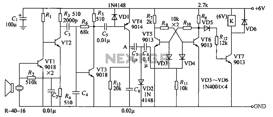
The circuit consists of transistors VT1 through VT7 and other components. Due to the weak signal received from the transmitter, the circuit employs a multi-stage amplifier to enhance the output. This output generates a square wave pulse signal to...
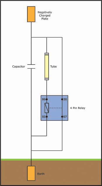
An individual has been studying Nikola Tesla's work for approximately 11 months and recently discovered Imhotep's concept of Radiant energy. The study of Nikola Tesla's contributions to electrical engineering and energy transmission has led to significant advancements in understanding electromagnetic...
SPI Integrated Circuit Bus, IC Buses, an IC, Chip-to-Chip Bus Serial Peripheral Interface, Integrated Circuit Bus types, and IC Bus Electrical Interface Descriptions. Peripheral Interface (SPI) circuit is a. The Serial Peripheral Interface (SPI) is a synchronous serial communication...
Most universal radio receivers have a very wide bandwidth that is not particularly suitable for radio amateurs. The better models with narrower bandwidth are almost a... Universal radio receivers are designed to operate over a broad frequency range, making them...
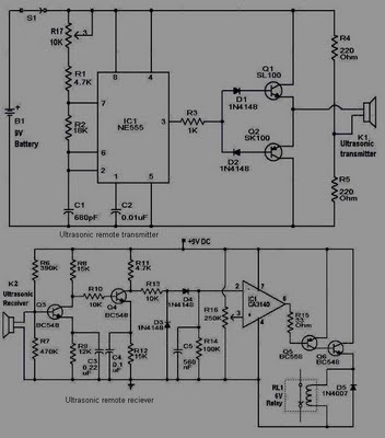
This circuit is straightforward and well-defined. The transmitter operates at 9 volts, while the receiver circuit functions at 5 volts. The transmitter utilizes a 555 timer and two SL100 transistors to perform its function. The receiver incorporates a small...