
Dummy Alarm Project

The Dummy Alarm circuit operates using a 7555 timer IC configured in astable mode. In this configuration, the timer generates a square wave output that controls the blinking of the LED. The timing components, typically a resistor and a capacitor, determine the frequency of the output signal. For a flash every 5 seconds, appropriate resistor and capacitor values must be selected. The LED is connected in series with a current-limiting resistor to ensure it operates within safe current limits.
When designing the circuit, it is crucial to select a super-bright red LED to maximize visibility while minimizing power consumption. The choice of a 7555 timer over a standard 555 timer is significant, as it allows for extended operation on battery power due to its lower current requirements.
The circuit can be powered by a variety of battery types, including alkaline AA cells or a PP3 9V battery, with the understanding that the resistor values must be adjusted accordingly to maintain the desired LED current. The resistor value can be calculated using Ohm's law, taking into account the supply voltage and the forward voltage drop of the LED.
In summary, the Dummy Alarm project is an efficient circuit that simulates an alarm indicator light with minimal power consumption, making it suitable for long-term use. Adjustments to the resistor values and choice of timer IC can further optimize performance based on available power sources.This Dummy Alarm project makes an LED flash briefly once every 5 seconds to imitate the indicator light of a real alarm. The circuit is designed to use very little current to prolong battery life so that it can be left on permanently.
An on/off switch is not included, but could be added if you wish. The 7555 timer IC used is a low power version of the standard 555 timer. A `superbright` red LED is used because this provides a bright flash with a low current. The LED is off for most of the time so the average total current for the circuit is less than 0. 2mA. With this very low current a set of 3 alkaline AA cells should last for several months, maybe as long as a year. The circuit will work with a standard 555 timer IC (such as the popular NE555) but this will increase the average current to about 2mA and the battery life will be much shorter.
You can use a greater supply voltage (15V maximum) for this circuit but the 1k resistor for the LED should be increased to keep the LED current low at about 3mA. For example to use a 9V PP3 battery change the 1k resistor to 3k3. Note that AA cells will last longer than a 9V PP3 battery. 🔗 External reference
Related Circuits
A circuit was assembled on a breadboard, which is divided into two sections. The right section is dedicated to generating a wailing alarm, while the left section is... The circuit design comprises two main functional blocks: the alarm generation circuit...
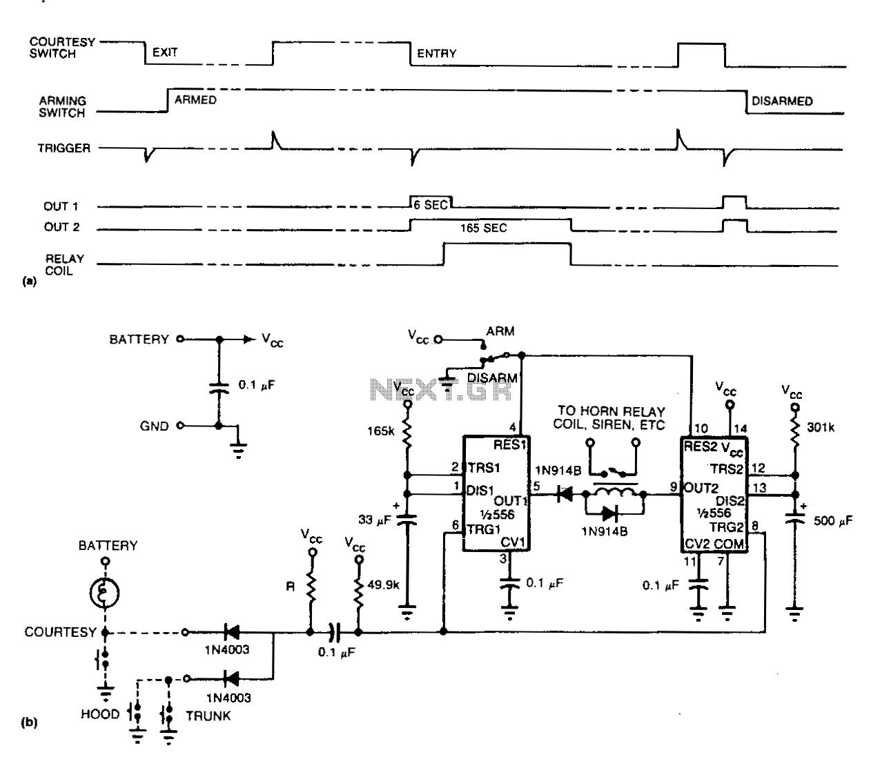
Refer to (a) for the timing information related to the alarm circuit depicted in (b). When departing from the vehicle, the arming switch should be flipped, and the door closed to activate the device. The subsequent opening of an...
The high and low voltage cut-off with delay and alarm circuit, along with its circuit diagram, is explained in this post. The high and low voltage cut-off circuit is designed to protect electrical devices from damage caused by excessive voltage...
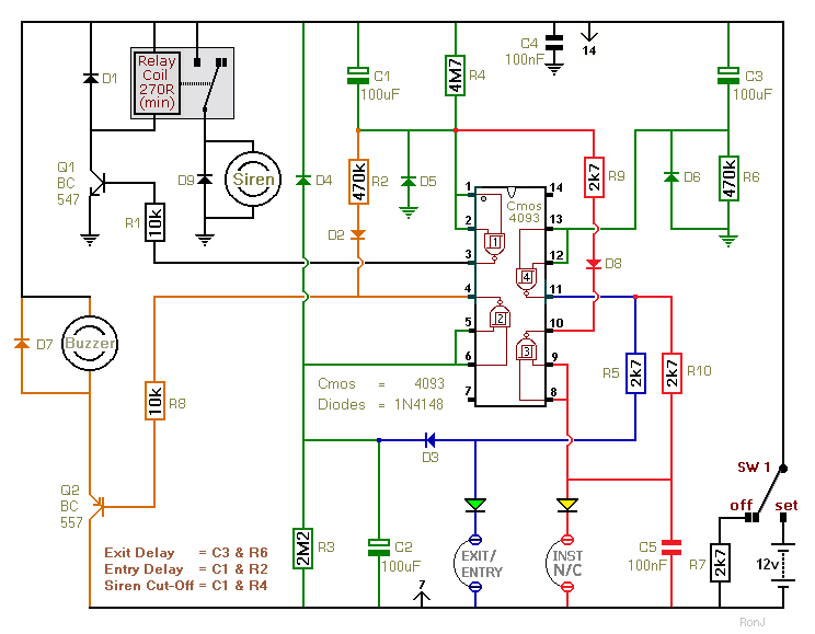
This is a two-zone alarm system featuring automatic exit, entry, and siren cut-off timers. It can be activated by standard normally-closed input devices such as magnetic reed contacts, foil tape, and passive infrared sensors (PIRs). The circuit is designed...
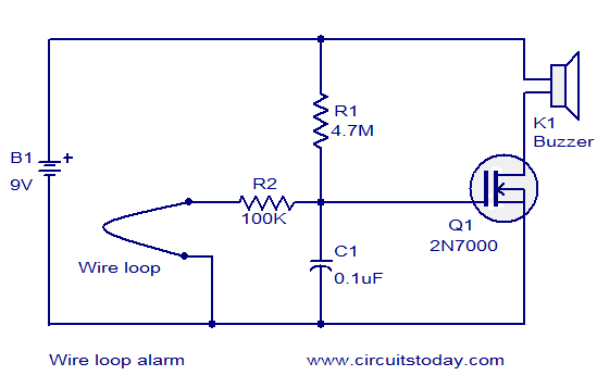
The circuit diagram illustrates a simple wire loop alarm utilizing an N-channel enhancement FET 2N700, a buzzer, and several passive components. Under normal conditions, the gate of the 2N700 (Q1) is connected to the ground through a 100K resistor...
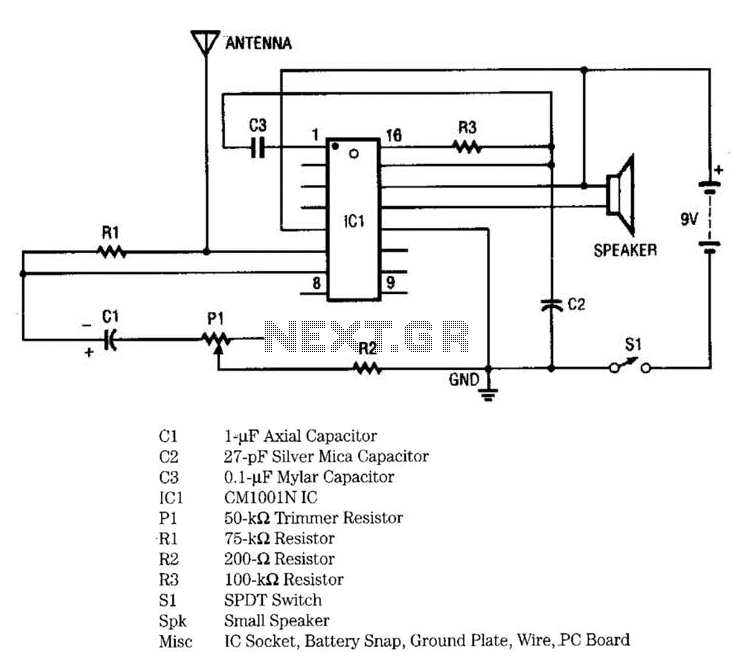
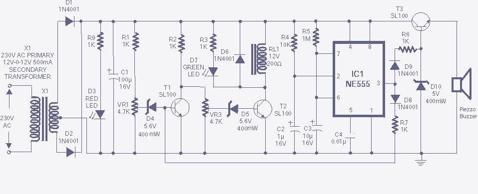
IC1 includes multiple oscillators and an amplifier. The low-frequency audio signal oscillator provides an input to the amplifier. This signal is the audio tone that is amplified and subsequently delivered to the speaker by the amplifier. The high-frequency oscillator...