
dvi to par digital video interface with lcd

The dvi2par also includes optional I2C EEPROM support, allowing it to be used with hosts other than the BeagleBoard, which supports the display's DDC/EDID configuration. However, this feature has only been verified to work on a standard Linux desktop PC. Since it is not necessary on the BeagleBoard, it has not been tested in detail. To use this feature, an EDID description for the specific display must be created using the Phoenix EDID Designer 1.3 (a Windows software that operates well in Wine). The output from this editor must then be programmed into the dvi2par DDC EEPROM. The jumper JP1 must be set to enable writing to the EEPROM. The I2C port of the HDMI connector should be connected to Linux-controlled I2C hardware, such as an I2C-tiny-USB.
The following components were sourced from Germany from Reichelt and Conrad:
- Part: HDMI connector, Quantity: 1, Reichelt Part No.: 530335-62
- Part: 3.3V regulator, Quantity: 1, Name: LM2937 ET3, Reichelt Part No.: 3
- Part: DDC EEPROM, Quantity: 1, Name: ST 24C01 MN
- Part: TFP101A, Quantity: 1
- Part: Capacitor (10uF/16V SMD), Quantity: 2, Name: TAN. 10/16
- Part: Capacitor (100nF), Quantity: 5, Name: X7R-G0805 100N
- Part: Resistor array (4*22R SMD), Quantity: 7, Name: BCN16 22
- Part: Resistor (4.7k SMD 0805), Quantity: 2, Name: 4.70K
- Part: Resistor (100R SMD 0805), Quantity: 1
- Part: Resistor (47k SMD 0805), Quantity: 2, Name: 47.0K
- Part: Diode (1N 4001 SMD), Quantity: 1, Name: 1N 4001 SV1-SV4, JP1-JP2
- Part: Pin header (1x36), Quantity: 1, Name: SL 1X36G 2.54
- Part: Power connector, Quantity: 1, Name: AKL 101-03
The circuit design involves integrating the TFP101A with the necessary components to ensure compatibility between the 1.8V signals and the 3.3V signals required by LCDs. The circuit must be carefully laid out to accommodate the routing of the SCDT signal to the backlight inverter, ensuring proper operation only when a valid HDMI signal is detected. The optional I2C EEPROM adds flexibility for different display configurations, enhancing the circuit's versatility across various platforms. Proper attention to the layout and connections, particularly regarding the I2C interface and EEPROM programming, is crucial for successful implementation.Unfortunatately this only provides 1. 8v signals and still needs a converter to interface to the 3. 3v signals most raw LCD use. The main components is the TFP101A. I got mine as a free sample from TI. Also visible in this picture is the fact that only the upper 6 of the 8 color bits available on the dvi2par are being used. It`s important to make sure that the upper bits are being used if the display supports less than 24 bit
color depth. Also visible in the image is the fact that a tiny wire goes from pin 8 of the TFP101A to some other parts on the board is mounted on. Pin 8 carries the SCDT signal which indicates that a valid signal has been detected in the input. In this example the signal is routed to the backlight inverter and makes sure that the backlight is only switched on if a valid HDMI signal is being received.
EDID/DDC support The dvi2par also includes an optional i2c eeprom which is meant to allow to use the dvi2par on hosts other than the beagleboard which support to use a displays ddc/edid configuration. However, this part has only been verified to be operational and to be usable on a standard linux desktop PC.
But since this part is not necessary on a beagleboard, it isn`t tested to all detail. In order to use it, you need to build an EDID description for your particular display using e. g. the Phoenix EDID designer 1. 3 (A windows software which runs fine in wine). The output of this editor needs then to be programmed into the dvi2par ddc eeprom. The jumper JP1 has to be set to enable writing the eeprom. The i2c port of the hdmi connector then needs to be connected to some linux controlled i2c hardware like e. g. my i2c-tiny-usb. Below is an image of my i2c-tiny-usb based adptor used to write the ddc eeprom on the dvi2par. All remaining parts have been bought in germany from Reichelt and Conrad. The part numbers are: Part Qty Name Reichelt Part No. Conrad Part No. X1 1 HDMI connector 530335-62 IC1 1 3. 3V regulator LM2937 ET3, 3 IC2 1 DDC eeprom ST 24C01 MN IC7 1 TFP101A C2, C3 2 Capacitor 10uF/16V SMD TAN.
10/16 C1, C4-C7 5 Capacitor 100nF X7R-G0805 100N RN1-RN7 7 Resistor array 4*22R SMD BCN16 22 R1, R3 2 Resistor 4k7 SMD 0805 4, 70K R2 1 Resistor 100R SMD 0805 100 R4, R5 2 Resistor 47k SMD 0805 47, 0K D1 1 Diode 1N 4001 SMD 1N 4001 SV1-SV4, JP1-JP2 1 Pinheader 1x36 SL 1X36G 2, 54 X2 1 Power connector AKL 101-03
Related Circuits
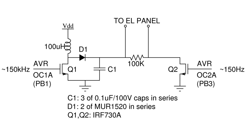
There are two primary types of backlights for LCDs: LEDs, which stands for light-emitting diodes, and EL, which stands for electroluminescent. EL backlights are generally more efficient and provide more uniform lighting compared to LED backlights, but they require...
The component is deformed due to various thermal influences during processing, which compromises the original machining accuracy and introduces errors. In precision finishing, the effect of thermal deformation is particularly significant, leading to processing errors that can exceed 40%....
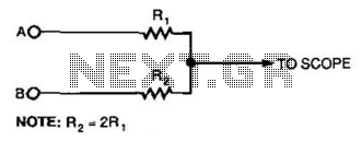
This simple resistor circuit can be used to trick an oscilloscope into displaying two logic signals on one channel. By selecting R2 to be twice the value of R, the oscilloscope trace will show one of four distinct analog...
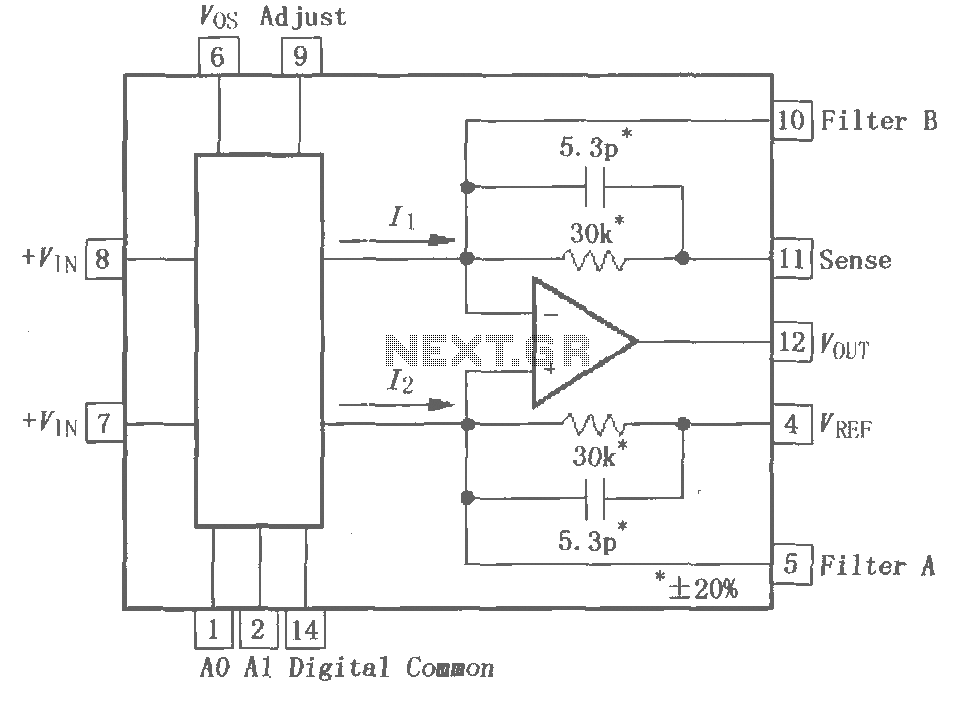
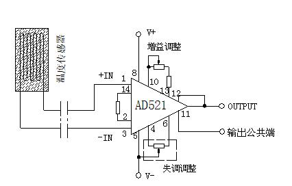
The PGA202 is a digitally controlled programmable gain amplifier with gain settings of G = 1, 10, 100, and 1000. The PGA203 offers gain settings of G = 1, 2, 4, and 8. Both amplifiers are compatible with CMOS...
Normally, an analog-to-digital converter (ADC) requires interfacing with a microprocessor to convert analog data into digital format. This involves additional hardware and software, leading to increased complexity and overall cost. The circuit of the A-to-D converter presented here is...
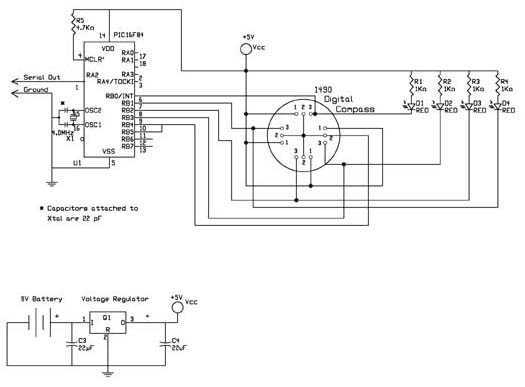
The digital navigation PC board may be configured for a number of navigation functions. It may be made into a simple visual digital compass, or a microcontroller based compass. The microcontroller based compass can be used for mobile robotics...