
Digital Compass for PC

The digital navigation PC board serves as a versatile platform for various navigation applications, primarily utilizing the 1490 digital compass sensor from Robson Company. This solid-state Hall effect sensor is adept at detecting the Earth's magnetic field, making it suitable for both simple visual compasses and more complex microcontroller-based systems.
In operation, the sensor can accurately indicate the four cardinal directions (N, S, E, W) and the intermediate directions (NE, NW, SE, SW) when the board is rotated. This capability is enhanced by a dampening mechanism that mimics the response of a traditional liquid-filled compass, reducing overshooting and providing stable readings. The built-in hysteresis feature further stabilizes output by preventing fluctuations when the sensor is near a directional threshold.
The 1490 sensor's design includes a sensitivity to tilt, which is a critical consideration in applications where the device may not be perfectly level. Any tilt exceeding 12 degrees can introduce significant directional inaccuracies, thus the installation and orientation of the board must be carefully managed.
The sensor's lead configuration consists of 12 pins organized into four groups of three. The first group of leads (labeled 1) is connected to a power supply of +5V (Vcc), while the second group (labeled 2) is grounded. The third group (labeled 3) serves as the output leads, functioning similarly to an open collector output of an NPN transistor. Each output can handle a continuous current of 20 mA, with a maximum intermittent current of 25 mA, allowing for reliable interfacing with microcontrollers or other processing units.
This configuration makes the digital navigation PC board an effective tool for mobile robotics, PC-based compass applications, and other navigation functions, providing both flexibility and precision in directional sensing.The digital navigation PC board may be configured for a number of navigation functions, see figure 1. It may be made into a simple visual digital compass, or a microcontroller based compass. The microcontroller based compass can be used for mobile robotics or a PC based compass. The sensor used on the PC Board is the 1490 digital compass manufactured by Robson Company, see figure 2.
This sensor is a solid-state Hall effect device. It is sensitive enough to detect the Earth's weak magnetic field. When rotated it can display the position of the four cardinal points on a compass, North (N), South (S), East (E) and West (W). As well as the intermediate directions: North East (NE), North West (NW), South East (SE), and South West (SW), see figure 3.
The sensor is dampened to approximate the speed of a liquid filled compass. The dampening prevents over swinging the direction. In addition the built in hysteresis prevents flutter when near a switching direction. The 1490 device is sensitive to tilt. Any tilt greater than 12 degrees will create directional errors. The bottom of the device has 12 leads arranged in four groups of three leads. Looking at the device from the top each group of leads are labeled 1, 2 and 3. The leads labeled 1 are connected to Vcc (+5V). Leads numbered 2 are connected to ground. And the leads labeled 3 are our output leads. The output leads of the device are equivalent to an open collector of an NPN transistor, see figure 4. Each output is capable of sinking 20 mA continuously or up to 25 mA intermittently. 🔗 External reference
Related Circuits
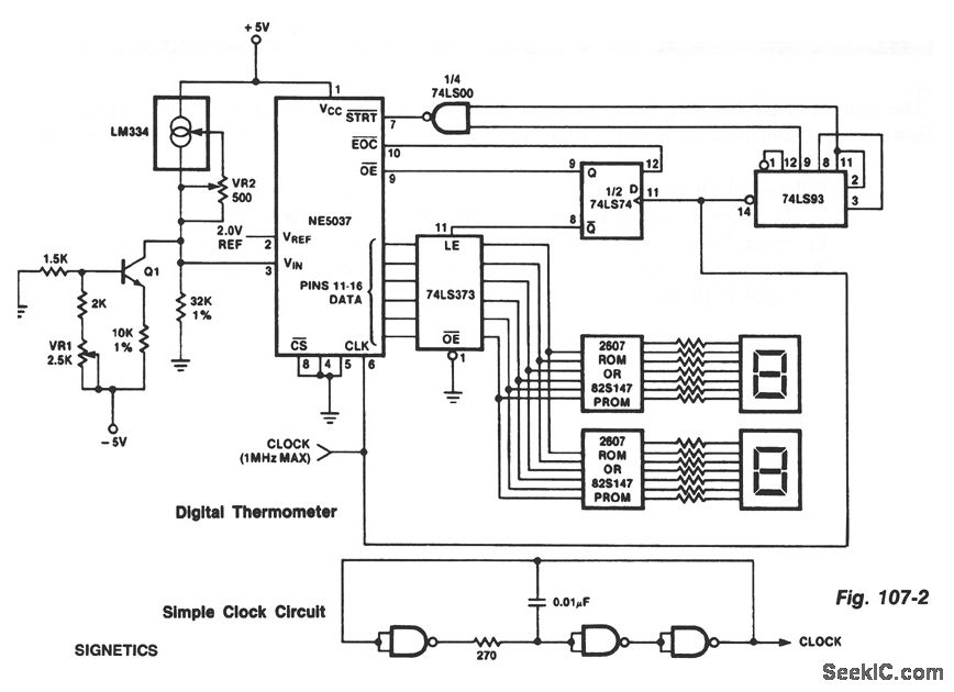
The ROMs or PROMs must contain the correct code for converting data from the NE5037, which serves as the address for the ROMs or PROMs, into the appropriate segment driver codes. The displayed temperature can be converted to degrees...
This digital thermometer indicates the temperature measured with an NTC using 7 LEDs. The circuit works using an opamp, the well-known 741, which amplifies the voltage difference between its plus and minus input. This amplification (sensitivity) can be set...
The circuit diagram for a multiple output digital camera power supply using the MAX1802 is illustrated below. The MAX1802 chip features two buck converters and three boost converters. It accepts an input voltage range of 2.5 to 11V and...
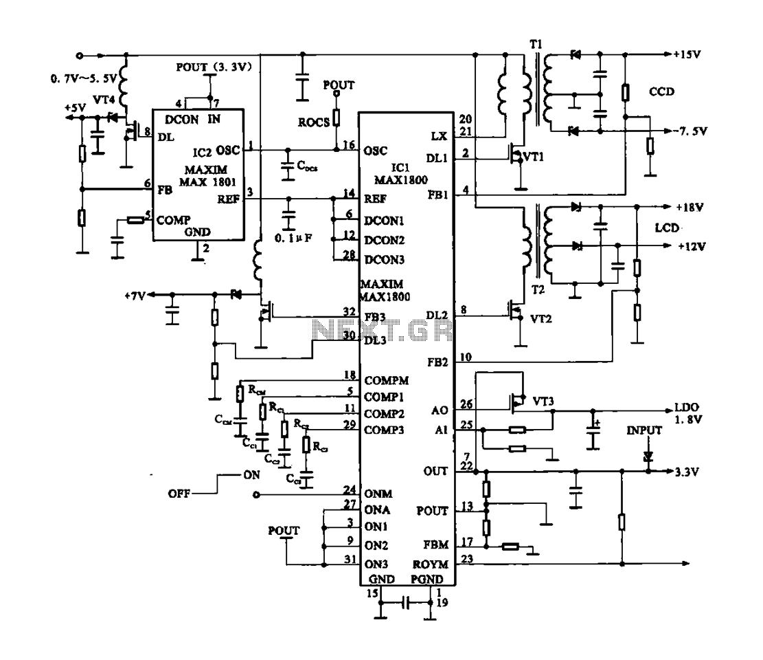
Digital Cameras - DV machine power supply circuit. This circuit utilizes the MAX1800 chip to manage the power supply for digital cameras and DV machines. Digital cameras are typically battery-operated and require low voltages ranging from 0.7 to 5.5...
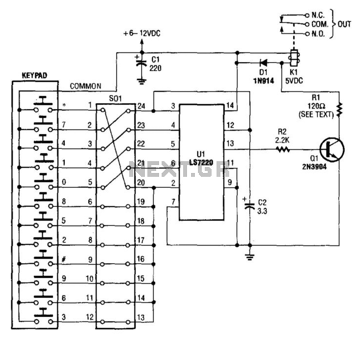
A keypad is used to input a four-digit access code, which is configured using jumpers on a 24-pin plug-in header and socket. The component Ul is an LST220, which detects a sequential four-digit data input. Upon successful entry of...
This digital DIY tachometer for bicycles utilizes two reed switches to gather speed information. The reed switches are positioned near the wheel rim, where permanent magnets, attached to the wheel spokes, pass by and activate the switches. The speed...