
Digital Countdown schematic with 555

The CD4510 is a CMOS Presettable BCD Up/Down counter which can be preset to any number between 0 and 9 with a high level on the PRESET ENABLE line, (pin 1) or reset to 0 with a high level on the RESET line (pin 9). Inputs for presetting the counter (P1, P2, P3, P4) are on pins (4, 12, 13, 3) respectively. The counter advances up or down on each positive-going clock transition (pin 15) and the counting direction (up or down) is controlled by the logic level on the UP/DOWN input (pin 10, high=up, low=down). The CARRY-IN signal (pin 5) disables the counter with a high logic level.
The CD4511 is a CMOS BCD to 7 segment latch decoder capable of sourcing up to 25 mA which allows it to drive LEDs and other displays directly. A LATCH-ENABLE line (pin 5, active low) stores data from the BCD input lines. A LAMP-TEST input (pin 3, active low) can be used to illuminate all 7 segments, and a BLANKING input (pin 4, active low) can be used to turn all segments off. The LED display must be a common cathode type so that the segments are illuminated with a positive voltage on their respective connections.
The circuit operates by utilizing a CD4010 up/down counter to track the countdown from 9 to 0. Initially, when the switch is closed, the counter is set to 9 through the preset inputs. The 555 timer, configured in astable mode, generates a clock pulse approximately every second when the switch is opened. This clock pulse is fed into the clock input of the CD4010, causing it to decrement its count on each pulse until it reaches 0.
Upon reaching 0, the carry-out signal at pin 7 transitions low, which activates a 12V relay. This relay can be used to control other devices or indicators, providing a physical response to the countdown completion. The reset line (pin 4) of the CD4010 is also driven low by the relay activation, halting the clock and preventing further counting until the switch is closed again, which resets the counter back to 9.
The 555 timer's timing characteristics can be fine-tuned by adjusting the resistor connected to pin 3, enabling slight modifications to the duration of the clock pulse. This flexibility allows for customization of the delay period according to specific requirements. The CD4511 decoder then takes the BCD output from the counter and drives a 7-segment display, providing a visual representation of the current count, enhancing usability and feedback for the user. The design ensures that the circuit is both functional and user-friendly, with clear indications of the countdown status.This circuit provides a visual 9 second delay using a 7 segment digital readout LED. When the switch is closed, the CD4010 up/down counter is preset to 9 and the 555 timer is disabled with the output held high. When the switch is opened, the timer produces an approximate 1 second clock signal, decrementing the counter until the 0 count is reached.
When the zero count is reached, the 'carry out' signal at pin 7 of the counter moves low, energizing the 12 volt relay and stopping the clock with a low signal on the reset line (pin 4). The relay will remain energized until the switch is again closed, resetting the counter to 9. The 1 second clock signal from the 555 timer can be adjusted slightly longer or shorter by increasing or decreasing the resistor value at pin 3 of the timer.
The CD4510 is a CMOS Presettable BCD Up/Down counter which can be preset to any number between 0 and 9 with a high level on the PRESET ENABLE line, (pin 1) or reset to 0 with a high level on the RESET line (pin 9). Inputs for presetting the counter (P1, P2, P3, P4) are on pins (4, 12, 13, 3) respectively. The counter advances up or down on each positive-going clock transition (pin 15) and the counting direction (up or down) is controlled by the logic level on the UP/DOWN input (pin 10, high=up, low=down).
The CARRY-IN signal (pin 5) disables the counter with a high logic level. The CD4511 is a CMOS BCD to 7 segment latch decoder capable of sourcing up to 25 mA which allows it to drive LEDs and other displays directly. A LATCH-ENABLE line (pin 5, active low) stores data from the BCD input lines. A LAMP-TEST input (pin 3, active low) can be used to illuminate all 7 segments, and a BLANKING input (pin 4, active low) can be used to turn all segments off.
The LED display must be a common cathode type so that the segments are illuminated with a positive voltage on their respective connections. 🔗 External reference
Related Circuits
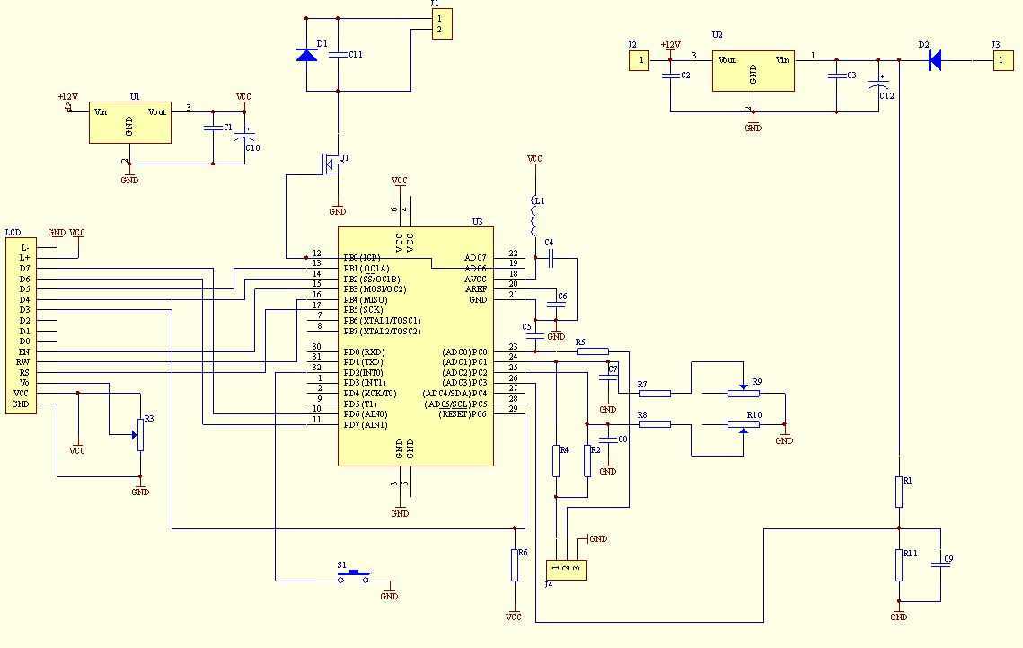
This multimeter was designed to measure output voltage and current in a PSU, where the current sense shunt resistor is connected in series with load at the negative voltage rail. It needs only one supply voltage that can be...
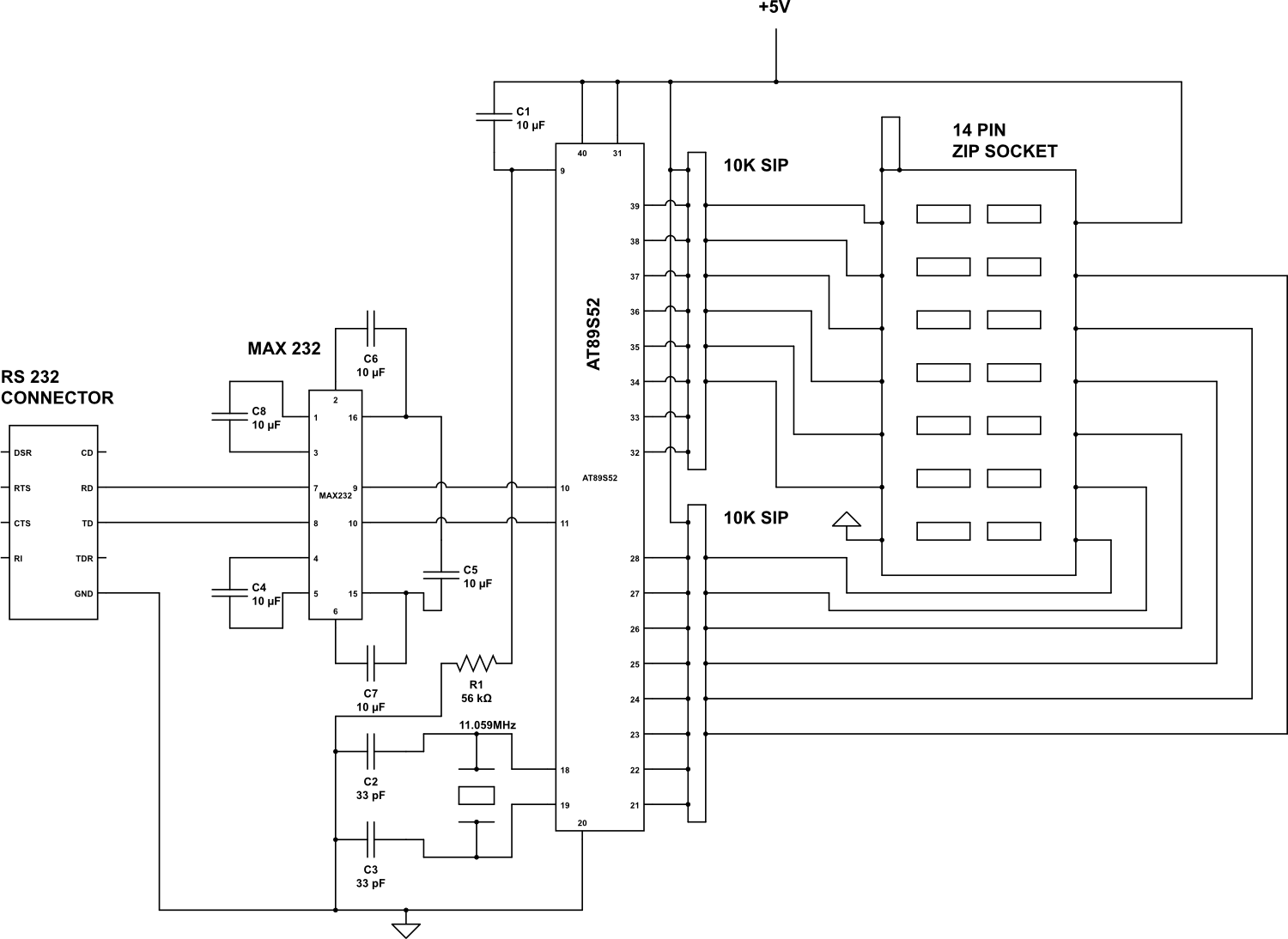
Check the following ICs: 7400, 7402, 7404, 7408, 7432, 7486. A Visual Basic program is utilized to display the results on the PC. The microcontroller AT89S52 receives the IC number from the PC, verifies the logic gates with the...
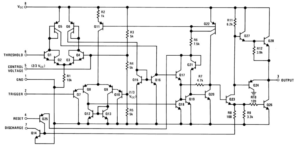
The 555 timer is a highly versatile integrated circuit that has found applications in a wide range of devices, from toys to spacecraft. This chip can function as an oscillator, a Schmitt trigger, and more. The 555 timer is a...

A digital stopwatch or digital timer circuit schematic is constructed using the timer IC LM555 and the 4-digit counter IC MM74C926, which is paired with a multiplexed 7-segment LED display. The digital stopwatch circuit utilizes the LM555 timer IC configured...
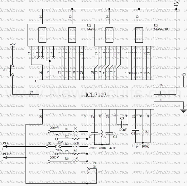
The ICL7107 is a 3 1/2 digit LED A/D converter. It contains an internal voltage reference, high isolation analog switches, sequential control logic, and the display drivers. The auto-zero adjust ensures zero reading for 0 volts input. The ICL7107 is...
Digital Remote Thermometer. The remote sensor transmits data through the mains supply. The temperature range is from 0.0 to 99.9 °C. Transmitter circuit diagram includes the following components: R1, R3 = 100K 1/4W resistors; R2 = 47Ω 1/4W resistor;...