
DW10M-200 400 600 type excitation switch control circuit

The DW10M de-excitation type switch is an advanced component designed for integration into automatic air circuit breaker systems, enhancing operational reliability and safety. Its transition from normally open to normally closed contact provides a robust mechanism for managing electrical loads and ensuring system stability.
The control circuit, as depicted in Figure 7-56, plays a crucial role in the functionality of the switch. The closing contactor, represented by KM, is responsible for establishing the electrical connection when activated. The closing coil (YC) energizes to engage the contactor, while the trip coil (YR) is essential for deactivating the circuit in the event of an overload or fault condition, ensuring protection of the connected electrical equipment.
The time relay (KT), specifically the JT3-11/5 model, introduces a delay mechanism that allows for controlled operation of the circuit, preventing immediate disconnection and allowing for transient conditions. This feature is particularly beneficial in applications where momentary fluctuations in load may occur.
Control switch SA governs the operation of various switch configurations, indicated as LW2-2-la, 4, 6a, 40, 20/F8, allowing for tailored control based on specific operational requirements. The indicator lights, Hi (green) and H2 (red), provide visual feedback on the operational status of the switch, facilitating quick diagnostics and monitoring.
The XD-2 component, operating at 110V and 8W, signifies the switch's compatibility with standard voltage levels, while the inclusion of a 2.5 kΩ resistor aids in current regulation and protection of sensitive components within the circuit.
Finally, terminal switches SQ1 and SQ2 complete the assembly, providing necessary connection points for external circuitry and ensuring seamless integration into broader electrical systems. The comprehensive design of the DW10M de-excitation type switch underscores its significance in modern electrical engineering applications, particularly in enhancing safety and efficiency in circuit management.DW10M de-excitation type switch is based on the DW10 automatic air circuit breaker on the normally open to normally closed contact is made. (1) DW10M-200,400, 600 de-excitation type switch control circuit circuit as shown in Figure 7-56. Figure, KM is closing contactor} YC is closing coil; YR for the trip coil; KT was time relay JT3- 11/5; SA controls switch LW2-2-la, 4,6a. 40,20/F8; Hi, H2 green, red XD-2,110V, 8W, attached resistor 2.5kfl; SQi, sQ2 the terminal switch.
Related Circuits
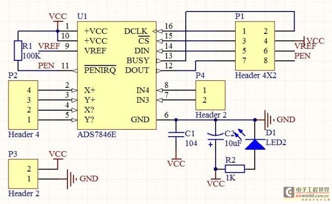
The touch control screen is a common feature in modern electronic products, typically incorporating a colored liquid crystal display (LCD) with a touch-sensitive interface. This technology is user-friendly and effectively replaces traditional fixed keypads. This document introduces the driving...

The Infrared IR Receiver circuit consists of a phototransistor, a microcontroller, and an amplifier. Understanding the data transfer between these three components is essential for successfully operating the circuit. The phototransistor receives digitally encoded data from an IR emitting...
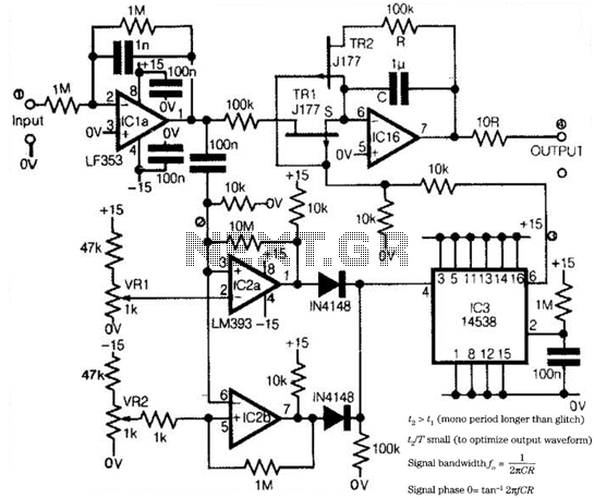
Low-frequency signals produced by transducers, measurement equipment, or data loggers often resemble the first waveform in the figure. The circuit operates as a tracking sample-and-hold, where transients are replaced in the output by the stored value of the current...
The 555 timer on the right is configured as an alarm sound generator, while the second 555 timer on the left operates as a 1 Hz astable multivibrator. The output from the left timer modulates the frequency of the...
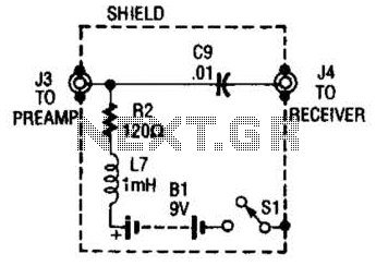
The purpose of the receiver/interface circuit is to pass RF to the receiver through capacitor C9, while adding DC power to the feedline through resistor R2 and RF choke L7. The receiver/interface circuit is designed to facilitate the transmission of...
The cooling is not only a PC using a small fan with an electronic commutator. A special feature of these fans is that their removal is less dependent on the load. Indicators monitoring the DC component of current may...