
Remote Doorbell Warning Switch circuit

This circuit design serves as a practical solution for enhancing doorbell notifications, particularly in environments where auditory signals may be overlooked. The primary components include a doorbell, a visual indicator (lamp or LED), and a series resistor (R1). The resistor plays a crucial role in managing the current flow to ensure the doorbell operates effectively while minimizing the power consumption from the power source.
The circuit configuration involves connecting the visual indicator in parallel with the doorbell. The series resistor R1 is then connected between the power source and the doorbell circuit. The choice of resistor values is critical; the combined resistance of a 22-ohm resistor in parallel with a 50-ohm resistor ensures that the voltage drop across R1 remains within the specified range. This configuration allows sufficient current to flow through the doorbell to activate it while providing enough voltage across the visual indicator for it to illuminate.
In practical applications, the visual indicator can be selected based on user preference, with options ranging from traditional incandescent lamps to energy-efficient LEDs. The latter option is particularly advantageous due to its lower power consumption and longer lifespan, further contributing to the overall efficiency of the circuit.
The use of an electromechanical counter in previous iterations of this design illustrates the potential for additional functionality. By integrating such a counter, users can track the frequency of doorbell activations, which may be beneficial for various applications, including monitoring visitor traffic in residential or commercial settings. Overall, this circuit design not only addresses the need for a visual alert system for doorbells but also offers opportunities for customization and expansion based on user requirements.It is quite easy to miss the sound of a doorbell if you are watching TV, this circuit gets round the problem by providing a visual indication, i. e. a lamp. As an alternative, a LED could also be used. You could just parallel a lamp across the doorbell, but this would mean extra drain from the doorb ell batteries or transformer. Using a series resistor R1 actually reduces current flow, and if run from batteries, will give them a longer life. The value of R1 is chosen so that about 0. 6 to 0. 7 volts is dropped across it, and the doorbell should still ring. I used a combination of a 22 ohm resistor in parallel with a 50 ohm. The doorbell still rang and circuit operated correctly. I used to have an electromechanical counter that registered each time when someone pressed the switch.
in fact, I remember a time when I had more "hits" at my doorbell then at my web site=:) 🔗 External reference
Related Circuits
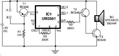
The UM3561 integrated circuit can be utilized to design various alarm systems with minimal electronic components. This UM3561 alarm electronic project requires only a few electronic parts and operates on a simple 3 volts DC power supply. The UM3561 is...

The circuit depicted in the figure includes IC1 and C1, which form a low-frequency oscillator operating at approximately 400 Hz. IC2 and C3 are configured to create a frequency oscillator around 37 MHz. The low-frequency signal is output from...
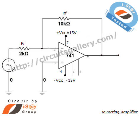
An inverting amplifier is one of the most widely used operational amplifier circuits. The output adjusts in a manner that counteracts changes caused by the input, thereby preventing saturation and ensuring stability. By connecting a resistor from the output...
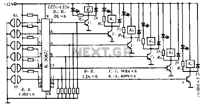
A, B, and C are used for a high-power split-phase system. The A + B' C' arrangement serves as a phase line for a range generator. The A-A' indole path string includes two 220V / 15W bulbs, which are...
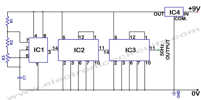
Accurate 50Hz Oscillator Circuit Using 555 and 7490. This circuit generates a 50Hz pulse. It consists of a 555 timer and two 7490 divide-by-ten counters. The circuit utilizes a 555 timer configured in astable mode to produce a square wave...
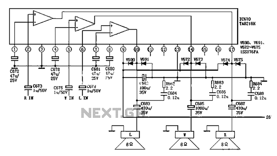
The audio circuit depicted in the figure is commonly utilized in color television systems. The pin functions and reference voltages for the TA8218AH are as follows: Pin 1: 1.9V - inverting input; Pin 2: 2.1V - R-channel audio signal...