
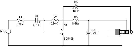
Dynamic Microphone Preamp PCB

This three-stage discrete amplifier circuit is designed to provide high gain and low noise for audio applications, particularly suitable for dynamic microphones. The first stage, Q1, operates in a common base configuration, which, while not typically used in audio applications, is effective in minimizing noise for low-level signals. The configuration allows for a low collector current, enhancing the input impedance to match dynamic microphones effectively.
The second and third stages, Q2 and Q3, are arranged in a direct-coupled configuration to maintain signal integrity and provide sufficient voltage gain. Q2 is configured as a common emitter amplifier, which contributes to the overall gain of the circuit, while Q3 serves as an emitter follower, ensuring a low output impedance. This arrangement is particularly beneficial for driving long cables without significant signal degradation.
The overall gain of approximately +39dB indicates a robust amplification capability, while the low-frequency roll-off at 30Hz ensures the circuit remains effective across a wide range of audio frequencies. The use of a 47k preset resistor allows for fine-tuning of the gain, providing flexibility based on the specific application requirements.
In terms of design considerations, the choice of transistors, biasing resistors, and supply voltage are critical in achieving the desired performance metrics. The calculated values for collector and emitter voltages, as well as the biasing stability against temperature variations, highlight the meticulous design approach taken to ensure consistent performance. Overall, this amplifier circuit is well-suited for applications requiring high fidelity and low noise amplification, particularly in professional audio contexts.This is a 3 stage discrete amplifier with gain control. Alternative transistors such as BC109C, BC548, BC549, BC549C may be used with little change in performance. The first stage built around Q1 operates in common base configuration. This is unusable in audio stages, but in this case, it allows Q1 to operate at low noise levels and improves overa
ll signal to noise ratio. Q2 and Q3 form a direct coupled amplifier, similar to my earlier mic preamp. As the signal from a dynamic microphone is low typically much less than 10mV, then there is little to be gained by setting the collector voltage voltage of Q1 to half the supply voltage. In power amplifiers, biasing to half the supply voltage allows for maximum voltage swing, and highest overload margin, but where input levels are low, any value in the linear part of the operating characteristics will suffice.
Here Q1 operates with a collector voltage of 2. 4V and a low collector current of around 200uA. This low collector current ensures low noise performance and also raises the input impedance of the stage to around 400 ohms. This is a good match for any dynamic microphone having an impedance`s between 200 and 600 ohms. The output impedance at Q3 is low, the graph of input and output impedance versus frequency is shown below: The overall gain of this pre-amplifier is around +39dB or about 90 times.
The first stage Q1 has a gain of roughly Rc / Re or 4. 7. This is however reduced by feeding into the input impedance of Q2 and Q3, and the shunt formed by the 47k preset. The amplifier formed with Q2 and Q3 has a gain of roughly Rc / Re as Q3 is an emitter follower and has unity gain.
The gain of Q2 and Q3 is roughly 10 / 0. 47 = 21 and overall gain therefore 4. 7 x 21 = 98. The gain of the circuit may be reduced to 0 by the 47k preset. The response is flat to 100kHz, low frequency rolloff at 30Hz, a simulated plot is shown below: Any amplifier will add its own noise to the signal, degrading the overall performance. The noise of this preamp measured with a 10k load resistor is shown below. The first stage, Q1 was designed to operate with a collector current of 200 uA. With 15k and 47k bias resistors and a 12 V supply voltage the base voltage will be 12 x ( 15 / (15+47) = 2.
9 Volts. The emitter voltage will be the base voltage -0. 7 V or 2. 2 V. For a 200 uA collector current the emitter resistor will be 2. 2 / 0. 2 mA =11k. A 10k resistor was used. As Ic and Ie are approximately equal then the collector voltage is 12 - (0. 2 * 47) = 2. 6 V. The last stage is a composite amplifier similar to my ECM preamp. Q2 operates in common emitter and provides the voltage gain while Q3 operates in emitter follower, buffering the output and has a low impedance output, suitable for driving long cables, if required. The last stage, Q3 was designed for maximum voltage swing, hence Q3 emitter voltage should be around 6V.
Variation in transistor parameters however, means that measured voltages will be different to calculated voltages. Q2 collector voltage is a base-emitter voltage drop higher or 6. 7 V and collector current is set at (12 - 6. 7) / 10k = 530 uA. This is also the emitter current for Q2 and hence emitter voltage will be ( 0. 53 * 0. 47) = 0. 24 V. The base voltage will be higher by 0. 7 V. As the base of Q2 is connected to the emitter of Q3, then the biasing is stabilized to a certain degree against changes in temperature and current gain variation.
However if a meter is available for testing transistor beta, then the transistor with the highest current gain should be used for Q2. 🔗 External reference
Related Circuits
Most sound card microphone inputs require a minimum signal level of at least 10 millivolts, but some older 8-bit cards need as much as 100 millivolts. The typical impedance of the PC sound card microphone input is in the...
Greetings to everyone. I am new to this forum, although I have previously used it to create a DIY projector. My knowledge of electronics is limited, and I am currently reading books to improve my understanding. The creation of a...
This circuit is designed for use with inductive pick-up elements and dynamic microphones. Most soundcards feature a line input and a dedicated input for electret (condenser) microphones. To connect an inductive tape recorder head or a dynamic microphone, an...
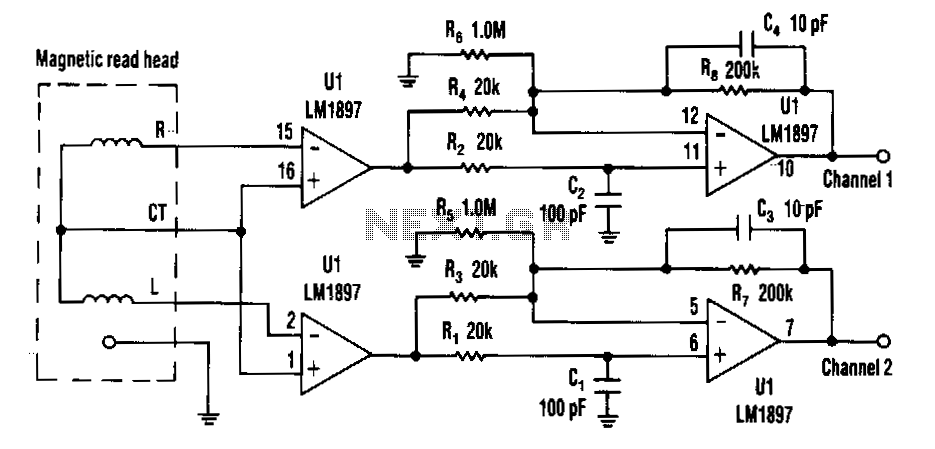
Choosing direct current (DC) coupling instead of alternating current (AC) coupling can significantly reduce the noise associated with preamplifiers for a magnetic reading head, particularly at low frequencies. The LM1897 eliminates the need for the capacitor that typically AC...
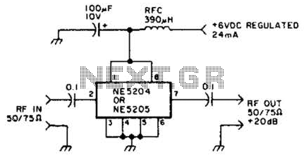
The Signetics NE5204 or NE5205 can be utilized in this audio frequency to 350-MHz (-30 dB) preamplifier. For a requirement of 600 MHz at 3 dB, the NE5205 should be employed. The noise figure is 4.8 dB at 75...
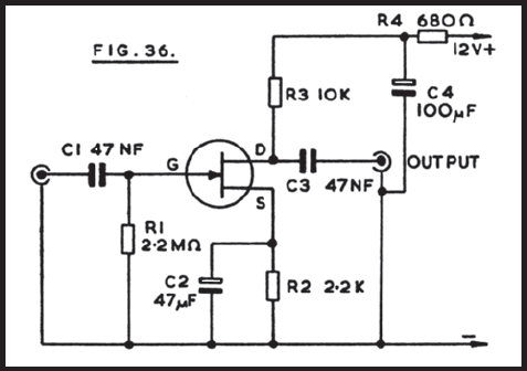
Figure 36 illustrates the circuit of a preamplifier featuring a high impedance input and an output circuit designed for coupling to a main amplifier. This configuration is particularly advantageous for applications such as amplifying the signal from a crystal...