
Ear Protector Circuit

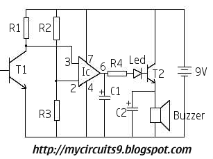
The ear protector circuit functions by continuously monitoring the output audio signal level from the amplifier. It employs a peak detector to assess whether the output volume exceeds a specified threshold. When the detected output level surpasses this threshold, the circuit triggers a shutdown mechanism that activates the chip-disable input of the amplifier. This effectively mutes or disables the amplifier, thereby protecting the connected audio output devices and preventing potential damage due to excessive volume levels.
The components typically involved in this circuit include resistors, capacitors, a diode for rectification, and the peak detection circuitry, which may consist of operational amplifiers or comparators. The design must ensure that the threshold level is adjustable to cater to various applications and user preferences.
In implementing this circuit, careful consideration should be given to the selection of the components to ensure compatibility with the specific amplifier IC being used. The peak detector's response time should also be optimized to ensure it reacts quickly enough to transients in the audio signal without causing unnecessary interruptions in audio playback.
For applications beyond the MC34119 amplifier, the circuit can be adapted by modifying the input and output connections as required while maintaining the core functionality of peak detection and shutdown. This versatility makes the ear protector circuit a valuable addition to any audio system where volume control and protection against clipping or distortion are critical. The ear protector is actually a peak audio-detector/shutdown circuit that disables the amplifier through its chip-disable input when the output volume of an amplifier reaches the set level. The circuit, although intended for the MC34119 amplifier, should work with similar IC devices or applications.
Related Circuits
Writing about multiple circuits in Marx, an entire new set has been discovered, referred to as "the" Marx Generator. There are diagrams available, along with a useful quote: "The main advantage of the Marx circuit configuration over a more...
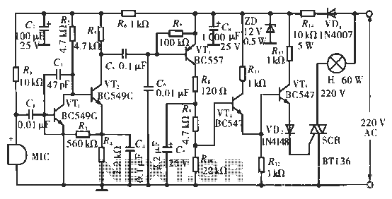
The circuit utilizes condenser microphones to detect sound and convert it into signal variations. This signal is then processed through directly coupled transistors VT1 and VT2, which form an amplification stage before being fed into a switching circuit. The...
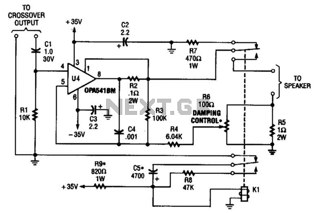
Designed to power a low-frequency subwoofer speaker system, the amplifier can deliver up to 100 W into an 8-ohm load. The OPA541BM operational amplifier, produced by Burr-Brown Corporation, necessitates heatsinking for optimal performance. Additionally, the design incorporates a damping...
This project has been specially designed to introduce you to SMD (Surface Mount Devices). Surface Mount is really not new. It started as far back as 1940 with a hybrid circuit in a digital watch. A chip was cemented...
This circuit activates an alarm whenever an object crosses the laser beam emitted by a laser. The output of the IC TL071 goes high when the laser beam is interrupted. This output voltage is further amplified by an NPN...
XTAL1 drives amplifier Q3/Q4, which is tuned to 2.25 MHz. The detected signal is fed to audio amplifier IC1. A 9-V supply is used. The circuit operates at 2.25 MHz and is designed to be used with an ultrasonic...