
LASER BURGLAR ALARM CIRCUIT

The described circuit functions as an intrusion detection system utilizing a laser beam as a sensing mechanism. The primary components include a laser diode as the transmitter, which emits a coherent light beam, and a phototransistor (L14F1) that serves as the receiver. The phototransistor is sensitive to the wavelength of the laser light and is positioned to directly receive the beam.
When the laser beam is uninterrupted, the phototransistor remains in a conductive state, allowing a low voltage signal to be sent to the operational amplifier (IC TL071). The operational amplifier is configured to compare the input voltage from the phototransistor against a reference voltage. In the absence of the laser light, for example, when an object crosses the beam, the output of the TL071 transitions to a high state, indicating an alarm condition.
The NPN transistor (Q2) is employed to amplify the output signal from the IC TL071. This amplification is essential to drive a buzzer or alarm system effectively. The buzzer is activated when the transistor is turned on, producing an audible alarm to notify of the intrusion.
For optimal performance, the circuit may require fine-tuning of the reference voltage at the TL071 to ensure sensitivity to the laser interruption. Additionally, the choice of laser and phototransistor should be made based on the operating environment and the required detection range. Overall, this laser-based alarm system presents a reliable solution for security applications, providing a straightforward method for detecting unauthorized access through the interruption of a laser beam.This circuit alarms whenever someone cross the Laser beam transmitted from a LASER. The output of IC TL071 goes high whenever their is no Light(Laser) Ray. This output voltage is further amplified by means of a NPN transistor Q2, which will drive the buzzer and generates an alarm. As i mentioned above, you can use an ordinary Laser as Transmitter and the circuit shown in the figure act as Receiver. The sensing or receivng part of this circuit consisting of a PhotoTransistor L14F1. It will detect Laser Beam and the output is given to IC TL071. Whenever an intruder cross or cuts the ray the circuit alarms. 🔗 External reference
Related Circuits

Active crossover circuit design, circuit diagram, schematic, DIY active crossover circuit, HiFi audio crossover, 2-way crossover circuit using LM833. The active crossover circuit is an essential component in high-fidelity audio systems, allowing for the separation of audio signals into different...

As shown in the generator start battery automatic monitor circuit diagram. The generator start battery automatic monitor circuit is designed to oversee the battery's status during generator operation. This circuit ensures that the battery remains charged and functional, preventing premature...
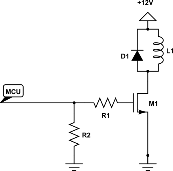
The solenoid requires a specific amount of current to generate its magnetic field. If the solenoid were a perfect inductor, the DC current could rise excessively and potentially damage other circuit components. However, solenoids inherently possess a significant amount...

The system utilizes a modular design featuring the AT89S52 microcontroller and CPLD as the central processing unit (CPU) for overall system coordination. Initially, it establishes a cycle of systematic pulse signals through a 4G-4 key set module, allowing for...

The circuit is presented, consisting of a language and sound circuit FM transmitter. It is simple and easy to manufacture, compatible with ordinary FM radios, allowing for potential listening scenarios and preventive measures. The FM transmitter circuit is designed to...

Figure 1-91 illustrates a practical loudness volume control circuit designed for integration with a preamplifier and tone control system. This circuit is positioned behind the output capacitor load (OCL) and can be connected to the main amplifier. Its effectiveness...