
Early VDO Tachometer Guts

The circuit functions as a monostable multivibrator, generating a single output pulse in response to an input trigger. The design incorporates a voltage regulator to ensure stable operation, particularly in the presence of voltage ripples from the alternator. The Zener diode plays a crucial role in voltage regulation, preventing over-voltage conditions that could damage sensitive components.
The timing characteristics of the circuit are influenced by the values of the resistors and capacitors. R5, which determines the discharge rate of C2, is critical in defining the pulse width output. The interaction between the capacitors, resistors, and transistors ensures that the output pulse width is proportional to the input frequency, which is essential for accurate tachometer readings.
The configuration of the transistors is such that Q1 acts as the primary switch, while Q2 serves to maintain the state of Q1 under certain conditions. The careful selection of component values is necessary to achieve the desired duty cycle and response time.
In practical applications, variations in component tolerances can lead to differences in performance, which may necessitate calibration or adjustment to achieve optimal operation. The circuit's design allows for flexibility in component selection, enabling adaptation for different vehicle models, such as the 911 and 912 tachometers.
Simulation tools like LTSpice can be used to analyze the circuit's behavior, although users may encounter challenges in achieving the expected output waveforms. Proper setup of the simulation parameters and understanding of the circuit's operation are essential for successful modeling. This circuit exemplifies the integration of analog components to create a reliable measurement system in automotive applications.The "crossed-flags" topology of a monostable multivibrator. Also, this particular board happened to be a 912 tach, so R5, which determines the discharge rate of C2,would be different for a 911. 912`s have a 50% duty cycle (four cylinders, 45 degrees of dwell or MARK time per ignition event- that`s 180 degrees total or 50% of 360 degrees of distributor rotation- another
way to think about it is in 360 degrees of distributor rotation there are four ignition events or 90 degrees per event, of which the points are closed and distributor output is HIGH for 45 degrees or 50% of that) For a 911 you want a 63% MARK time, the points are closed 38 out of 60 degrees. With the car running +14V present on the voltage regulator circuit at the lower left. The Zener (value unknown at this point) has a breakdown voltage of a certain amount which limits the voltage on the top rail and the capacitor wired in parallel smooths out variations in voltage (ripple from the alternator that`s not damped out by the ship`s battery) Both the base of Q1 and Q2 are connected to the emitter of Q3 (I`m going to call this "ground" in the discussion below) through 2.
2K resistors but slight variances in the circuit mean one of them turns on first, it doesn`t matter. Suppose Q1 saturates first, its base is connected to ground through R5. Its collector gets pulled up above ground to positive voltage. This positive voltage is connected to the base of Q2, holding Q2 OFF. Next, a positive pulse arrives at the /1 terminal from the points. This goes through R8 and R6/R7 wired in parallel to the base of Q1, turning it OFF (thanks Loren for the clarification). Eventually C2 is fully charged and no more current flows, so the base of Q1 drops to ground through the 2.
2K resistor and C2 acts like a battery and discharges through the wire wound resistor (the number of turns of wire is a calibration element), resistor and thermistor in parallel and the meter movement, blipping the needle, completing the circuit through R5. I THINK this is right, but am open to corrections or suggestions. I have a model of this circuit in SWCAD III, a free circuit simulator, if anyone wants to try it, send me a PM.
( I can`t make it work, even though the circuit checks OK, I don`t have enough training with circuit simulators). Rick, I actually have been working with LTSpice, still don`t have all the bugs worked out. I get the circuit to check fine with netlist, and the operating points all have voltages- but for some reason I don`t get the nice square wave you do, I get a strange looking current pulse I(Rmeter), the blue trace, measured at the "meter.
" You used a 1V pulsed input as voltage control for the "switch", shown as V(points_d), the green trace, but it doesn`t matter if you use 100V (like Loren said above)- same waveform. BTW there is no "switch" model in LTSpice, thank heaven for the Internet where you can find out how to define a model on the diagram.
Cool! It was also a big help, I didnt` know how to define the transient analysis parameters, but I just copied them from your screen capture until I got it to work. Ditto the "switch. " Rick, I actually have been working with LTSpice, still don`t have all the bugs worked out. I get the circuit to check fine with netlist, and the operating points all have voltages- but for some reason I don`t get the nice square wave you do, I get a strange looking current pulse I(Rmeter), the blue trace, measured at the "meter.
" There must be something wrong in the area of the power supply also. I think that Q1, the Zener and the resistors are supposed to supply a constant voltage across the monostable so that the average value of the const pulse width signal is linearly proportional to the frequency. Does 🔗 External reference
Related Circuits
The tachometer, also known as a revolution counter, is an instrument that measures the speed of rotating machinery, typically expressed in revolutions per minute (RPM). This project involves creating a custom sensor using a light-emitting diode (LED) as a...
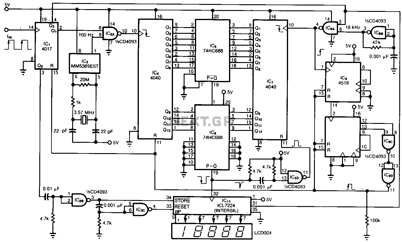
This tachometer allows for the measurement of heartbeats, respiratory rates, and other low-frequency events that occur at intervals ranging from 0.33 to 40.96 seconds. The circuit detects the frequency, calculates the corresponding pulses per minute, and updates the LCD...
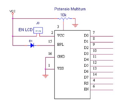
Pin 3 defines the Display type: Common Cathode or Common Anode. Connect this pin to GROUND if you are using common cathode 7-segment led displays. To use common anode displays, connect it to VCC (positive). Pin 4 is the...
A 2004 Chevy Tahoe lost power while driving at 60 mph, causing the tachometer to drop to zero. The vehicle has been in the shop for three days, and the mechanics are struggling to identify the issue. They have...
Pulses are received by the timer from the distributor points. When the timer output is high, Meter M receives a calibrated current through R6. The meter does not... The circuit described involves a timer that receives pulse signals from distributor...
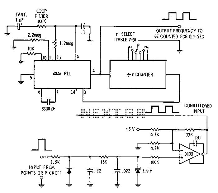
Automotive engine pulse points or other sensors are filtered using the transmission device 3130 CMOS operational amplifier, which functions as a comparator to fulfill the input conditions. The pulse subsequently flows into a 4046 phase-locked loop (PLL) N-counter, which...