
Easy Crystal Impedance Checker Circuit

Testing the equivalent series resistance (Rs) of a crystal oscillator is crucial for ensuring compatibility with microprocessors and microcomputers. Incompatible crystals may lead to malfunctioning circuits, which can compromise the performance of electronic devices. The described testing setup leverages a sweep generator to provide a frequency signal that is varied until it matches the resonant frequency of the crystal under test. An oscilloscope is employed to visualize the output signals, allowing for real-time analysis of the crystal's behavior.
The three resistors in the circuit serve specific roles: one acts as a reference resistor, while the others may be used to create voltage dividers or limit current in the testing circuit. The relationship between the amplitudes of output 1 and output 2 provides critical information about the crystal's Rs value. If output 2 surpasses output 1, it indicates that the crystal's Rs is lower than the reference, suggesting it is suitable for use. If output 2 does not exceed output 1, this indicates that the Rs is too high, which could lead to inefficiencies or failure in the oscillator circuit.
This testing method is advantageous due to its simplicity and effectiveness, allowing engineers to quickly ascertain the suitability of a crystal for a given microprocessor application. Proper selection and testing of crystals can significantly enhance the reliability and performance of electronic systems, particularly in timing applications where precision is paramount. On occasion, microprocessors/microcomputers and microprocessor crystals just aren`t compatible with each other. Many microprocessor data sheets specify maximum values for a crystal`s equivalent series resistance (Rs) that aren`t met by some crystals advertised for microprocessor/ microcomputer use.
As a result, a crystal with an Rs value greater than the maximum specified for the chip might cause problems, such as a balky or even inoperative clock oscillator. To tackle this problem, a suspected crystal can be given a quick check for Rs with a simple test setup that consists of a sweep generator, oscilloscope, and three resistors (see the figure).
When the frequency source is brought to the crystal`s frequency, output 2 will maximize. If it exceeds the amplitude of output 1, the crystal`s Rs value will be less than the Rs reference resistor`s value. If it doesn`t exceed output l`s amplitude, the crystal`s Rs value is too large.
Related Circuits
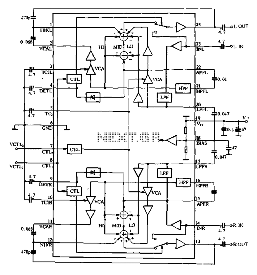
The BA3884 operates with a DC voltage range of 5.4 to 12.3V. Its internal circuit design and application circuit are represented in Figure 5-16. This circuit consists of a dual-channel processing system, which processes audio signals through two identical...
Adding this combination audio circuit, as illustrated in figure 14-38, to the automatic rhythm generator of electronic musical instruments fulfills the players' demand for incorporating drum and cymbal audio, enhancing the overall performance effect. The diagram indicates that the...
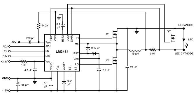
The LM3434 adaptive constant on-time DC/DC buck (step-down) constant current controller can be used to design a simple high-power LED driver application. The LM3434 provides a constant current for illuminating high-power LEDs. The output configuration allows the anodes of...
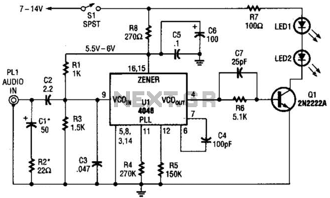
The transmitter for the wireless headphones is constructed using a CD4046 CMOS phase-locked loop, which is paired with a driver transistor and a set of infrared LEDs. While the CD4046 contains two phase comparators, a voltage-controlled oscillator (VCO), a...
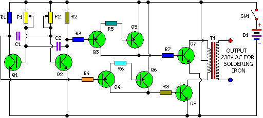
This is a simple and cost-effective inverter designed for small soldering irons (25W, 35W, etc.) to be used in the absence of mains supply. The circuit employs eight transistors along with a few resistors and capacitors. Transistors Q1 and...
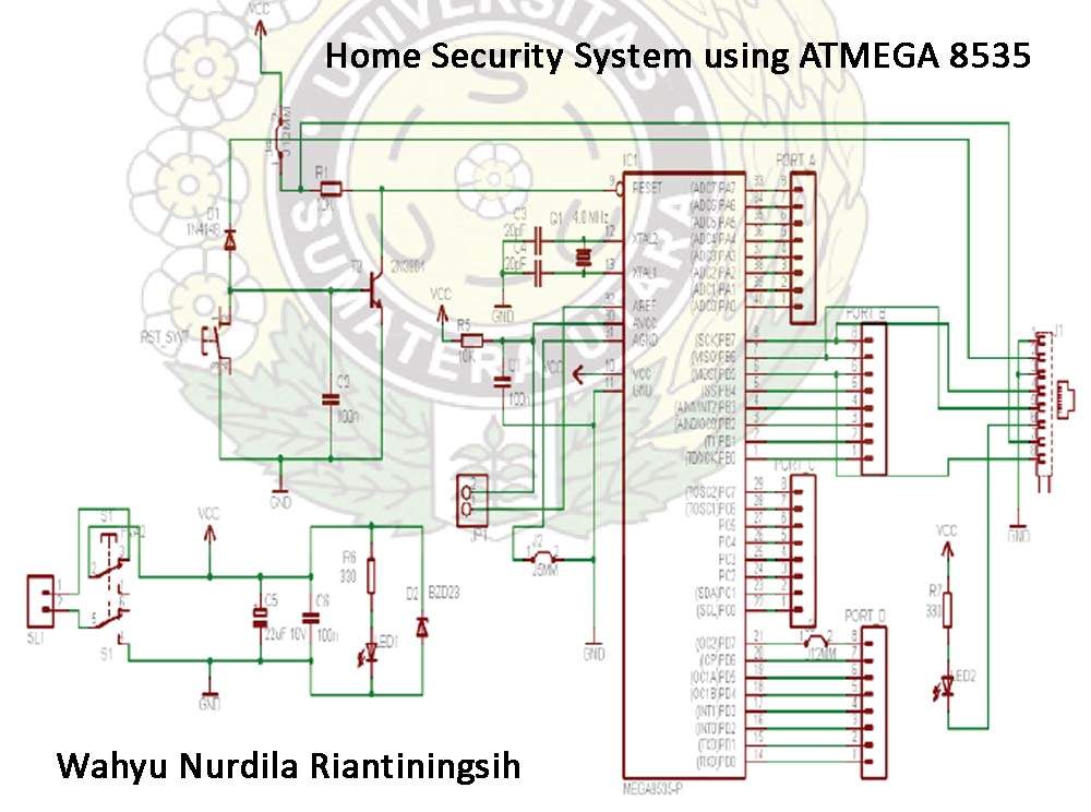
The Atmega 8535 Color Conversion to Frequency project utilizes instrumentation technology to recognize colors, also known as a color sensor, which is essential in various industrial applications. This sensor has multiple uses, ranging from the paint industry to satellite...