
Small wattage Inverter (Inverter Circuit For Soldering Iron)
")
The inverter circuit operates by converting a 12V DC supply from the battery into a 230V AC output suitable for powering small soldering irons. The astable multivibrator configuration formed by transistors Q1 and Q2 generates a square wave output at a frequency of 50Hz, which is essential for the operation of the soldering iron. The use of Darlington pairs Q3-Q5 and Q4-Q6 enhances the current gain, allowing the circuit to drive larger currents necessary for the power transistors Q7 and Q8.
Transistors Q7 and Q8, being 2N3055, are robust power transistors capable of handling high current loads. Their push-pull configuration enables efficient operation, minimizing distortion in the output waveform. The inclusion of heat sinks for these transistors is critical, as they will dissipate significant heat during operation, ensuring reliability and longevity of the components.
The transformer T1 plays a vital role in the circuit, stepping down the voltage to a safe level while providing the necessary current. The center-tapped configuration of the secondary winding allows for easy connection to the battery and facilitates the alternating current output needed for the soldering iron.
When assembling the circuit, careful attention should be paid to the layout on the PCB to minimize noise and interference. Proper gauge wires should be used for connections to handle the current without overheating. The selection of the battery must also align with the expected load to ensure adequate performance and operational time.
Finally, the user interface, including the power switch and the socket for the soldering iron, should be designed for safety and ease of use, ensuring that the inverter can be operated without risk of electrical hazards. Overall, this inverter design provides a practical solution for operating small soldering irons in environments where mains power is unavailable.Here is a simple but inexpensive inverter for a small soldering iron (25W, 35W, etc) In the absence of mains supply. It uses eight transistors and a few resistors and capacitors. Transistors Q1 and Q2 (each BC547) form an astable multivibrator that produces 50Hz signal. The complementary outputs from the collectors of transistors Q1 and Q2 are fed to pnp Darlington driver stages formed by transistor pairs Q3-Q5 and Q4-Q6 (utilising BC558 and BD140). The outputs from the drivers are fed to transistors Q7 and Q8 (each 2N3055) connected for push-pull operation.
Use suitable heat-sinks for transistors Q5 through Q8. A 230V AC primary to 12V-0-12V, 4. 5A secondary transformer (T1) is used. The centre-tapped terminal of the secondary of the transformer is connected to the battery (12V, 7Ah), while the other two terminals of the secondary are connected to the collectors of power transistors T7 and T8, respectively. When you power the circuit using switch S1, transformer X1 produces 230V AC at its primary terminal. This voltage can be used to heat your soldering iron. Assemble the circuit on a generalpurpose PCB and house in a suitable cabinet. Connect the battery and transformer with suitable current-carrying wires. On the front panel of the box, fit power switch S1 and a 3-pin socket for connecting the soldering iron.
Note that the ratings of the battery, transistors T7 and T8, and transformer may vary as these all depend on the load (soldering iron). 🔗 External reference
Related Circuits
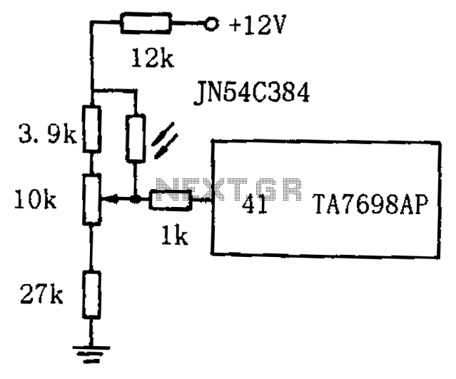
The circuit for automatic brightness adjustment in a television utilizes a photosensitive resistor and a contrast potentiometer connected to an intermediate stage. The photosensitive resistor varies its resistance based on light intensity, causing changes in the potential at the...
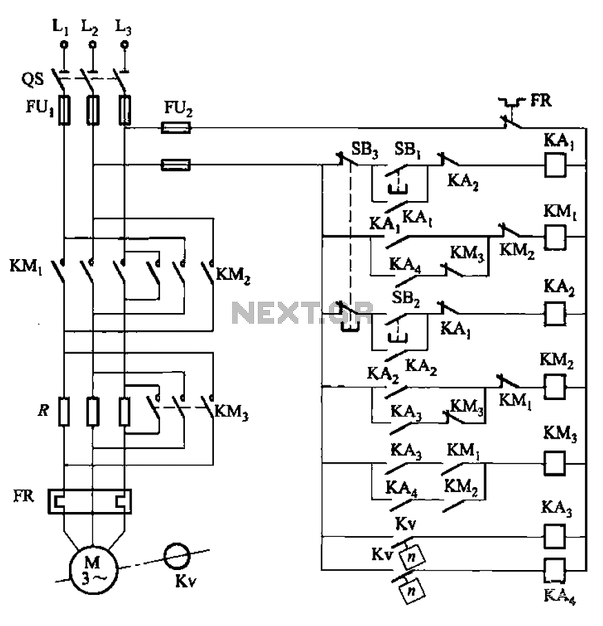
The circuit illustrated in Figure 3-130 differs from the circuit in Figure 3-129 in that when the stop button SB3 is pressed, the electric motor initiates braking. Furthermore, during both the startup and braking phases, the motor power lines...
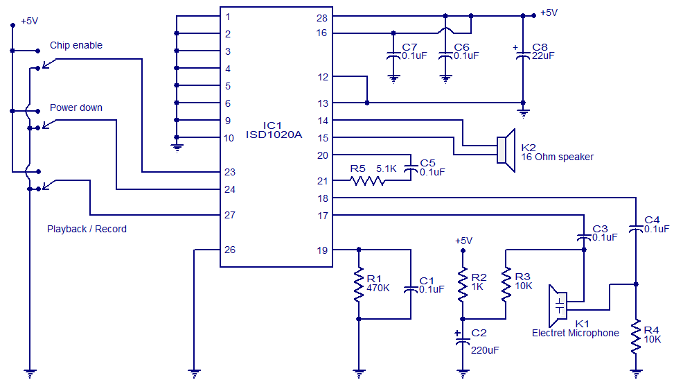
This circuit is designed in response to a request made by Mr. Vignesh for a voice recording and playback system. The circuit utilizes the ISD1020A IC from ISD, which is a CMOS single-chip record/playback device capable of recording voice...
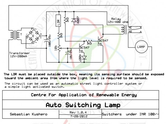
The circuit is designed to switch off a specific lamp or a group of lamps based on varying ambient light levels. Once constructed, it will turn off a lamp at dawn and turn it on at dusk. The power...
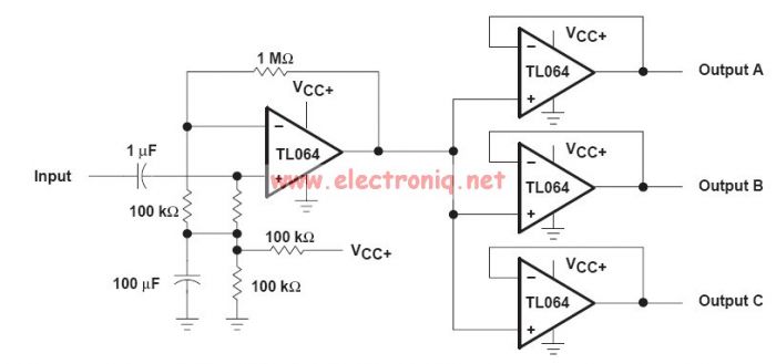
This audio distribution electronic project circuit diagram is designed using the TL064 or TL06 operational amplifiers and some other common electronic parts. The audio distribution circuit utilizes TL064 or TL06 operational amplifiers, which are quad op-amps known for their low...
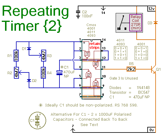
This circuit is based on a simple asymmetric oscillator. The duration for which the relay remains energized and the duration for which it remains de-energized are independently set. With the component values indicated in the diagram, both durations are...