
ECG FM demodulator circuit diagram

The described circuit serves a critical role in the transmission of medical data, particularly ECG signals, over satellite communications. The bandwidth of 0.5 to 50 Hz is specifically chosen to accommodate the frequency characteristics of ECG signals, which are essential for monitoring heart activity. The use of an audio signal as the FM signal source allows for efficient modulation, utilizing frequency modulation techniques to encode the ECG data onto a carrier wave.
The voltage-controlled oscillator (VCO) operates at a nominal frequency of 1 kHz, which is suitable for the modulation of low-frequency medical signals. The VCO's ability to deviate by ± 40% from its center frequency ensures that the circuit can adapt to variations in the input signal amplitude, thereby maintaining signal integrity during transmission. This frequency deviation is crucial for accurately representing the ECG waveform and other medical data, ensuring that the information received is both reliable and precise.
At the receiving end of the system, the corresponding audio signal is demodulated to retrieve the transmitted ECG data. This process involves filtering and amplification stages to ensure that the received signal is clear and free from noise, which is vital in medical applications where data accuracy is paramount. The overall design emphasizes low power consumption and high fidelity, making it suitable for use in portable and remote medical monitoring systems.
In summary, this circuit is a sophisticated solution for satellite-based transmission of vital medical data, leveraging FM modulation techniques and robust signal processing to ensure accurate and reliable communication of ECG signals.The circuit is suitable for satellite to transmit the ECG with bandwidth in 0.5 ~ 50Hz or other medical data in electronic systems. Audio signal is used as FM signal source applied to the 1KHz voltage controlled oscillator: when the input is maximum, the oscillator frequency deviation is ± 40%.
In the receiving place, the corresponding audio signal is sent.. 🔗 External reference
Related Circuits

The circuit amplifier and attenuator control video detector consists of a composition for the synchronization channel. The synchronization interval is where the gain circuit is increased. The described circuit involves an amplifier and an attenuator that work together to control...

When the ignition switch is activated, relay K1 receives continuous power, allowing the headlights to be turned on. When the ignition is turned off, timer IC1 is activated, maintaining its power for a duration determined by resistor R1 and...
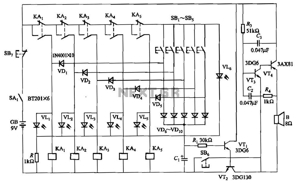
A relay-style circuit designed for a five electronic responder group. This circuit features self-locking capabilities, sound and light displays, time monitoring, and additional functions. The circuit includes a monitoring time button operated by the moderator. When this button is...
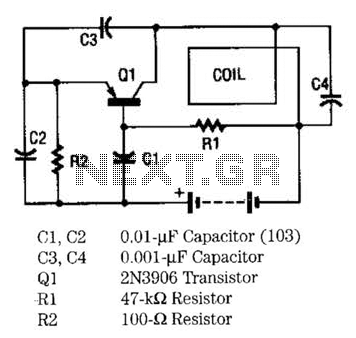
The metal locator utilizes a one-transistor oscillator in conjunction with an AM radio to detect metal. Transistor Q1 is a PNP transistor connected to the oscillator circuit. Resistor R1 supplies the appropriate base bias, while capacitors C3 and C4,...
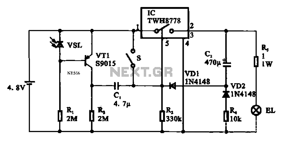
Automatic emergency lamp circuit featuring an electronic switch integrated circuit. This circuit is designed for automatic emergency lighting. The system operates based on ambient light conditions; when light levels are low at night, the circuit activates the emergency lamp....
The Reaction Capability Tester is utilized to assess and enhance an individual's quick-response abilities. It features various designs, with the depicted model comprising a CD4017 decimal counter and a light-emitting diode (LED). The construction of the Reaction Capability Tester...