
Electronics - circuit relay type answer

The relay-style five electronic responder group circuit is engineered to facilitate interactive sessions where participants respond to questions. The core of the circuit consists of five responder units, each equipped with a relay that activates upon receiving a signal. This setup allows for simultaneous participation from multiple users, enhancing the engagement of the event.
The self-locking feature ensures that once a participant has activated their responder, it remains engaged until it is intentionally reset, preventing accidental multiple submissions. The sound and light display serves as an effective means of communication, providing visual and auditory cues to participants regarding the status of their responses.
The monitoring time button, operated by the moderator, plays a crucial role in managing the flow of the session. When activated, an audio announcement is made, clearly indicating to all participants that the time for submitting responses is over. This feature is vital in maintaining order and ensuring that all participants adhere to the time constraints.
The SB7 button is strategically integrated into the circuit to allow the host to manage the session effectively. When a question has been thoroughly answered or when the time limit has been reached, the host can press this button to reset the circuit. This action prepares the system for the next question or round, ensuring a seamless transition and maintaining engagement throughout the session.
Overall, the design of this relay-style responder circuit is aimed at enhancing interactive experiences, providing clear communication, and ensuring effective time management during events. The combination of self-locking mechanisms, audio cues, and host control buttons contributes to a well-organized and efficient response system.A relay-style five electronic Responder Responder group circuit. The circuit has a self-locking, sound and light display, monitor time and other functions. Large ones may be in creased. Drawing, buttons SBe is monitoring time button by the moderator master. Press this button, audio circuit voice, told Time has come to stop writing ; button SB7 role is when the question answered, or because of the time to stop to answer, the host press the button briefly, the circuit recovery.
Related Circuits
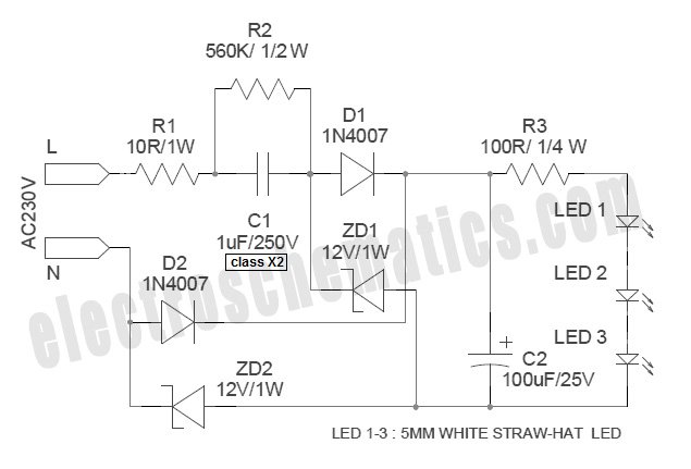
White Light Emitting Diodes (LEDs) now available can serve as a strong alternative to incandescent lamps in lighting applications. Today's White LEDs are... White Light Emitting Diodes (LEDs) represent a significant advancement in lighting technology, offering energy efficiency, longevity, and...
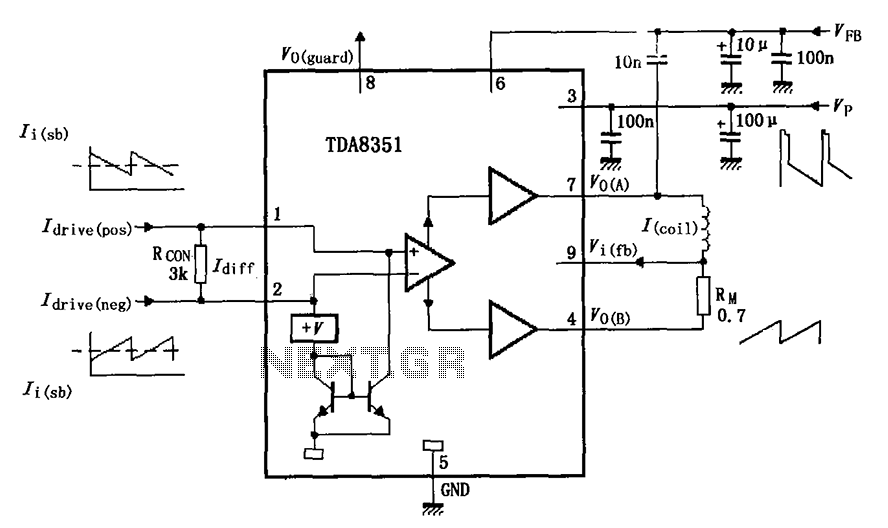
The figure illustrates the actual application circuit for the TDA8351/8356. In this circuit, a 50V voltage feedback (VFB) is connected in series with a 33-ohm resistor. Signals are input at pins 1 and 2, where pin 1 receives a...
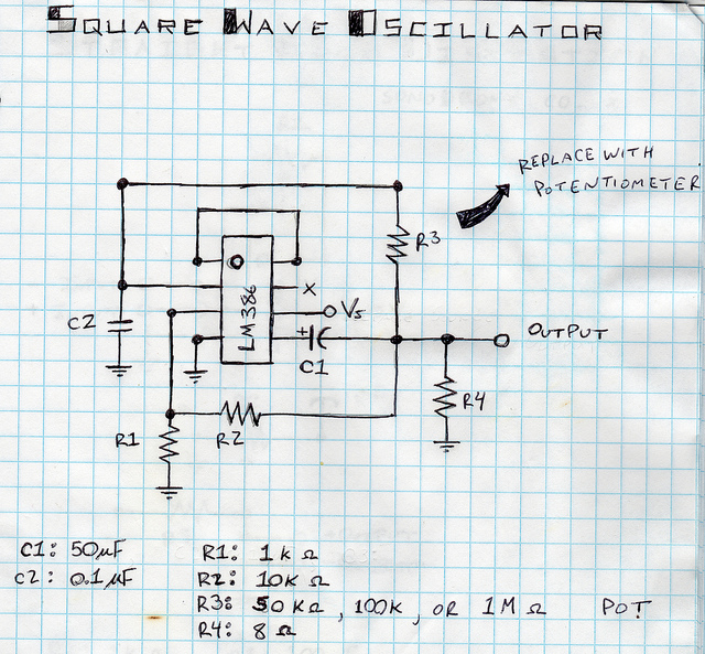
This is a square wave oscillator (digital, similar to 8-bit music). It is based on the LM386 amplifier integrated circuit, which is also the foundation for the mini guitar amplifier. The design includes a simple power switch connected to...

The circuit described is a crystal oscillation circuit using a CM OS inverting configuration, designed to ensure accurate operation. It employs a BCD counter (IC2) capable of achieving a maximum oscillation frequency of 2 MHz, which is 100 times...
Build the LC oscillator shown at the bottom of this page for a school project, but there are some challenges in translating the theoretical circuit into a real-world application. The understanding of the circuit's operation on paper is clear....
This circuit diagram illustrates a light-activated switch utilizing the National Semiconductor comparator IC LM311 and a light-dependent resistor (LDR). The configuration is based on a voltage comparator circuit centered around IC1. The non-inverting input of IC1 receives a reference...