
ECM Mic Preamplifier

The circuit utilizes low-noise transistors to achieve high fidelity audio amplification, which is critical in applications requiring precise sound reproduction. The choice of BC549C or BC109C as substitutes for the BC650C allows for flexibility in component sourcing while maintaining performance integrity. The self-stabilizing feature of the circuit ensures that variations in supply voltage do not adversely affect the quiescent point, thus enhancing the reliability of the amplifier.
The electret condenser microphone, with its internal FET preamp, is designed to operate efficiently within the specified voltage range, making it compatible with a variety of power supplies. The current-limiting resistor plays a vital role in protecting the microphone from excessive current, particularly when higher supply voltages are employed. The design effectively accommodates both three-terminal and two-terminal ECMs, ensuring versatility in microphone selection.
The first-stage amplifier's low collector current operation is a significant design choice, as it minimizes thermal noise and maximizes the signal-to-noise ratio. The decoupling of the emitter resistor with a capacitor further enhances gain, making the amplifier suitable for capturing faint audio signals. The direct coupling of the second-stage amplifier mitigates phase shift issues, resulting in a broader frequency response, which is essential for accurate audio reproduction across a wide spectrum.
The feedback mechanism from Q2 to Q1 not only stabilizes bias but also contributes to the overall performance of the amplifier, ensuring consistent operation across varying environmental conditions. The overall voltage gain of approximately 100x is indicative of the circuit's ability to amplify weak signals effectively, while the low output impedance facilitates long cable runs without significant signal degradation.
The PCB design, created using KiCad, exemplifies good engineering practices by providing a clear layout that minimizes interference and optimizes component placement. The inclusion of a silk screen layer aids in the assembly process, ensuring that components are correctly positioned. The availability of the design files in a zip package allows for easy reproduction and modification by other engineers or hobbyists interested in building or adapting the circuit for their specific applications.Both transistors should be low noise types. In the original circuit, I used BC650C which is an ultra low noise device. These transistors are now hard to find but BC549C or BC109C are a good replacement. The circuit is self stabilizing and will set its quiescent point at roughly half the supply voltage at the emitter of Q2. This allows maximum outp ut voltage swing and also the highest dynamic range. The electret condenser microphone (ECM) contains a very sensitive microphone element and an internal FET preamp, a power supply in the range 2 to 10 volts DC is therefore necessary. Suitable ECM`s may be obtained from Maplin Electronics. Although the schematic is drawn showing a three terminal ECM, two terminal ECM`s may be used, the following page in the practical section shows the changes.
The 1k resistor limits the current to the mic. This resistor should be increased to 2k2 if a supply voltage above 12 Volts DC is used and is not needed if the Mic insert is dynamic. The first stage amplifier built around Q1 is run at a very low collector current. This factor contributes to a very high overall signal to noise ratio and low overall noise output. The emitter resistor of Q1 is decoupled by the 100u realizing a maximum gain for this stage. The noise response of the amplifier measured across the 10k load is shown below. Please note that this plot was made with the mic insert replaced by a signal generator. The second stage, built around Q2 is direct coupled, this minimizes phase shift effects (introduced with capacitive and inductive coupling methods) and achieves a flat output response from 20Hz to over 100kHz.
The frequency response measured across a 10k load resistor is plotted below simulated using a 12V power source: The emitter voltage of Q2 is also fed back to the base of Q1 via resistive coupling. This also ensures bias stabilization against temperature effects. Q2 operates in emitter follower mode, the voltage gain of this stage is less than unity, however, the overall voltage gain of the preamplifier is about 100x or 20dB as shown in the bode plot above.
The output impedance is very low and well suited to driving cables over distances up to 50 meters. Screened cable therefore is not necessary. This preamplifier has excellent dynamic range and can cope with anything from a whisper to a loud shout, however care should be taken to make sure that the auxiliary equipment i. e. amplifier or tape deck does not overload. The following single sided PCB layout was created with Kicad, a free open source schematic and PCB drafting program.
Its available for both windows and linux, the image below is a 3D (enlarged) view of the component side. The copper layer (solder side) is the dark green layer on the bottom of the board. The top view (component side) of the PCB board is shown below. This is without the 3D components, the silk screen (drawings on the component side) allow for size of physical components.
The pin nearest R1 is the power for 3 terminal ECM`s. If a 2 terminal ECM is used then this pin also needs to connect to the centre pin on C1, for more info see the tutorial. The image below is an actual size (1:1) copy of the copper layer. Note that this is reverse so the veropins appear now on the left hand side at the top. Remember that this is the lower (solder) side, by viewing the top image you should be able to match up the positions of all components.
Finally you may not like my layout and prefer to create your own. The follwing am_rec. zip file, contains the schematic, component list and pcbnew diagram in one convenient zip file. 🔗 External reference
Related Circuits
Microphone amplifier schematic diagram. This circuit has been tested with three microphones: one from SONY and two from Chinese manufacturers, and it operates successfully with all. When assembled correctly, the device functions immediately without the need for tuning. The microphone...
Connecting a condenser capsule to the grid of a tube amplifier to build a tube microphone. This section discusses how to connect a capsule with two diaphragms to achieve a multi-pattern microphone. First, the different pickup patterns are examined:...
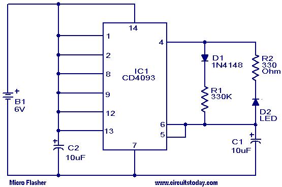
This micro flasher circuit continuously emits a flashing light while consuming very little power. The circuit can operate for an extended period using four 1.5V torch cells. A low-power CMOS IC, the CD4093 (IC1), is utilized to generate sharp...
A buzzer circuit utilizes a PIC microcontroller to drive a piezo buzzer. The microcontroller is a low-power processor that is ideal for portable and compact devices where battery conservation is essential. The buzzer circuit employs a PIC microcontroller, which serves...
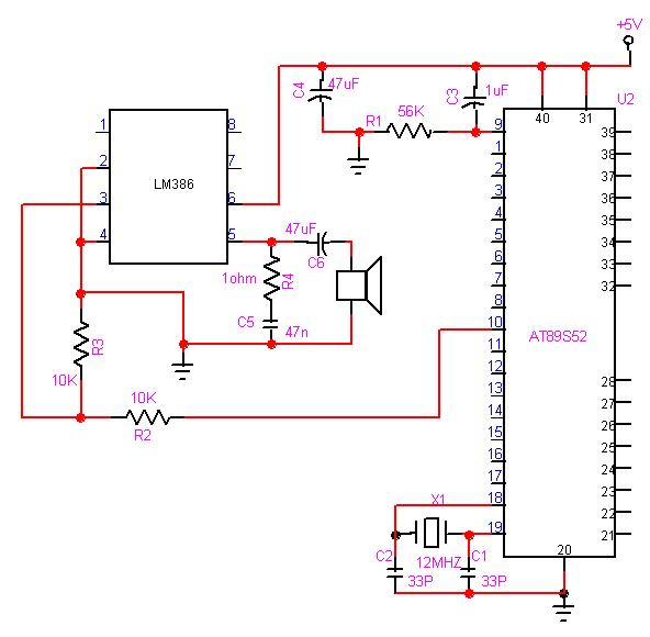
The 8051 microcontroller can play music tones. Here is a sample circuit and code that will play the music for "wishes you to be..." The 8051 microcontroller is a versatile and widely used microcontroller in embedded systems, capable of performing...
The LM4844 is an integrated audio subsystem designed for stereo cell phone applications. Operating on a 3.3V supply, it combines a stereo speaker amplifier delivering 495mW per channel into an 8Ω load and a stereo OCL headphone amplifier delivering...