
Tube mic Connecting the capsule 2

The construction of a tube microphone with multiple pickup patterns involves careful consideration of the design and functionality of the microphone's components. The use of condenser capsules with dual diaphragms allows for the creation of various directional characteristics, enhancing the microphone's versatility in different recording environments. The arrangement of the capsules is critical; positioning them back-to-back facilitates the mixing of their outputs in a manner that can produce the desired sound pickup pattern.
In practical applications, the U47 and U48 models serve as benchmarks for this design philosophy. The U47's approach to grounding the front diaphragm while polarizing the backplate creates a stable reference for the cardioid pattern, while the switch mechanism allows for straightforward toggling between cardioid and omnidirectional settings. This simplicity in operation is essential for users who may require quick adjustments while recording.
The U48's implementation of figure-of-eight pattern necessitates a more complex circuit due to the requirement of inverting the rear diaphragm's polarity. This inversion is crucial for achieving the desired sound cancellation at the microphone's sides, allowing for focused sound capture from the front and rear. The addition of a blocking capacitor is a vital step to ensure that the differing potentials of the diaphragms do not interfere with one another, thereby preserving the integrity of the audio signal.
To facilitate the variable pattern functionality, the adjustable supply voltage offers users the ability to fine-tune the microphone's characteristics in real-time. This feature is particularly beneficial in professional recording settings where adaptability to different sound sources and environments is paramount. The integration of such technology into the power supply, as seen in the Neumann-Gefell UM57, exemplifies the innovative approaches taken in modern microphone design, providing users with enhanced control over their recording capabilities. Overall, the design and operation of multi-pattern tube microphones represent a sophisticated blend of electrical engineering and acoustic principles, allowing for a broad range of applications in audio recording.Connecting a condenser capsule to the grid of a tube amplifier, in order to build a tube mic. In this part we consider how to connect a capsule with two diaphragms in order to get a multi-pattern mic. First let`s examine the different pickup patterns available. There are three extremes: Omni, where the microphone hears sounds equally in all directions. Cardioid (heart shaped*), where sensitivity is greatest in the direction in which the microphone is pointing, falling off to a null point behind. And Figure-of-Eight, with equal (but opposite) pickup in front and behind, and null pickup to the sides. To complicate things further, the pickup pattern may depend upon the frequency, and some mics will have good directionality at higher frequencies, but become less directional as the frequency drops.
But what if we want a microphone with selectable pattern This can be achieved by arranging a pair of cardioid capsules back-to-back, and combining there signals in different ways. We`ll call these capsules front and back, although of course they could be pointing in any direction.
If we require a cardioid signal, we just take the front capsule and for omnidirectional pickup, we mix both signals equally. If we want figure of eight, we subtract the output of the rear from the front: where the signals overlap at the sides of the microphone, they cancel each other out producing null points.
Other patterns such as hyper-cardioid and super-cardioid may be considered as in-between positions of these extremes. So, what is the best way to achieve this practically in our hypothetical tube microphone Two of the earliest commercial mics with more than one pattern were the Neumann U47, which offered cardioid and omni, and the U48, with cardioid & fig.
8. Let`s look at the U47, as this is probably the simplest way to combine the two capsules. In the U47 the front diaphragm is grounded through a 100 Meg grid resistor, and the backplate of the microphone`s dual diaphragm is polarised with about 60V, providing the potential difference required. The rear diaphragm is connected to a switch. When the switch is open, the rear capsule is left floating and only the front cardioid diaphragm is active.
When the switch is closed, the rear capsule adds its contribution to the front, making an omnidirectional microphone. What about the U48 We have seen above that if we require figure of 8 instead of omnidirectional, we must subtract, rather than add, the sounds from the rear.
To do this we must invert the polarity of the rear diaphragm by reversing its relative charge. So, rather than grounding the rear diaphragm, we must raise the potential by 60V* above the backplate, and 120V above the front capsule! This is easily achieved by using the HT supply to the anode of the tube, but creates another problem.
We can`t simply connect the two diaphragms because they are now at different potentials, and so a blocking capacitor must be used. The circuit looks like this: Finally, to make the microphone have variable pattern, we simply need to make a supply that is adjustable from 0V to 120V, and apply that to the backplate.
Alternatively, the signal may be taken from the backplate, through a capacitor to the tube grid. The Neumann-Gefell UM57 does it exactly this way, with the pattern selector in the power supply. 🔗 External reference
Related Circuits
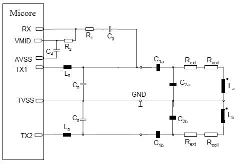
This document provides guidance on designing an antenna for the MICORE contactless reader IC family, which includes the MF RC500, MF RC530, MF RC531, SL RC 400, and CL RC 632. The antenna design and matching process is consistent...

The AT89C51-12PI is a variant of the AT89C51 microcontroller. For further details, please refer to the AT89C51 description. The datasheet for the AT89C51-12PI can be downloaded from the link provided below. This component is produced by ATMEL Corporation. The AT89C51-12PI...
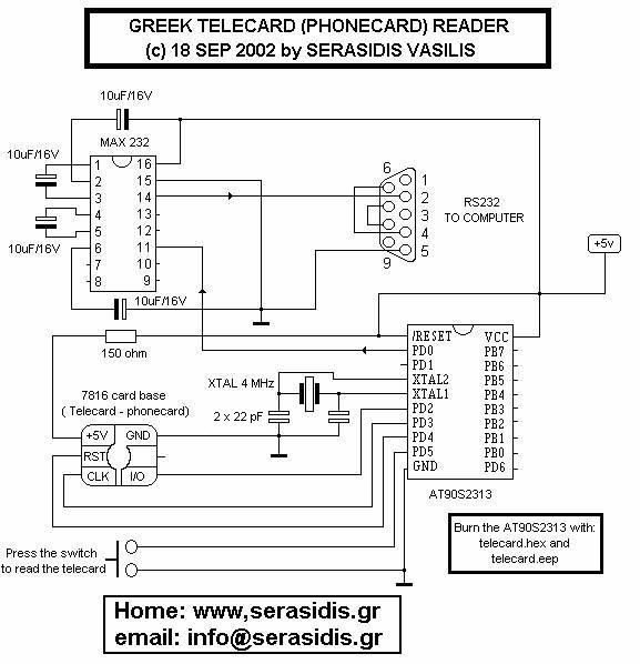
This circuit functions solely as a reader and is not designed for programming. It cannot be used to refill, hack, or perform any illegal activities with telecards. The primary purpose of this circuit is to demonstrate how a microcontroller...
A stepper motor is an effective solution for achieving high-precision motion control. To operate a stepper motor, a corresponding control circuit is required. A stepper motor control circuit typically consists of several key components that facilitate the precise movement of...
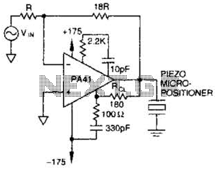
The PA41 from Apex Microtechnology is utilized to drive a piezoelectric micropositioner. The drive voltage is less than 20 V peak-to-peak at the input. The PA41 is a high-performance power amplifier designed specifically for driving piezoelectric devices, which require precise...
The circuit described is a discharge delay circuit that offers a longer delay compared to a standard rechargeable delay circuit, while also maintaining relatively high accuracy. The schematic diagram illustrates the input and output waveforms. Typically, when there is...