
Edge Avoider Robot without microcontroller

The Edge Avoider Robot (EAR) operates using a combination of sensors and microcontroller technology to navigate its environment effectively. The primary function of the EAR is to prevent it from falling off edges, such as tables or staircases, by utilizing proximity sensors that detect the presence of a surface. These sensors are typically mounted on the front and sides of the robot, allowing it to sense the distance to nearby edges.
In terms of circuit design, the EAR can be constructed using a microcontroller, such as an Arduino or Raspberry Pi, which processes the sensor inputs and controls the motors that drive the robot. The sensors used may include infrared (IR) or ultrasonic distance sensors, which emit signals and measure the time it takes for the signals to reflect back. This information is crucial for determining the proximity of the edge.
The power supply for the EAR can be achieved through rechargeable batteries, ensuring that the device remains mobile. The motors are usually controlled via a motor driver circuit, which can handle the current requirements of the motors while allowing the microcontroller to send control signals.
The software aspect involves programming the microcontroller to interpret sensor data and make real-time decisions on motor control. The robot can be programmed with various algorithms to enhance its edge-avoiding capabilities, such as simple reactive behaviors or more complex navigation strategies.
Overall, the Edge Avoider Robot is a practical application of basic robotics principles, integrating hardware and software to achieve a specific task of edge detection and avoidance. This project not only serves as an educational tool for understanding robotics but also demonstrates the importance of sensor integration and control systems in mobile devices.Edge Avoider Robot (EAR) is a mobile device, which senses and avoids the absence of surface below it.. 🔗 External reference
Related Circuits
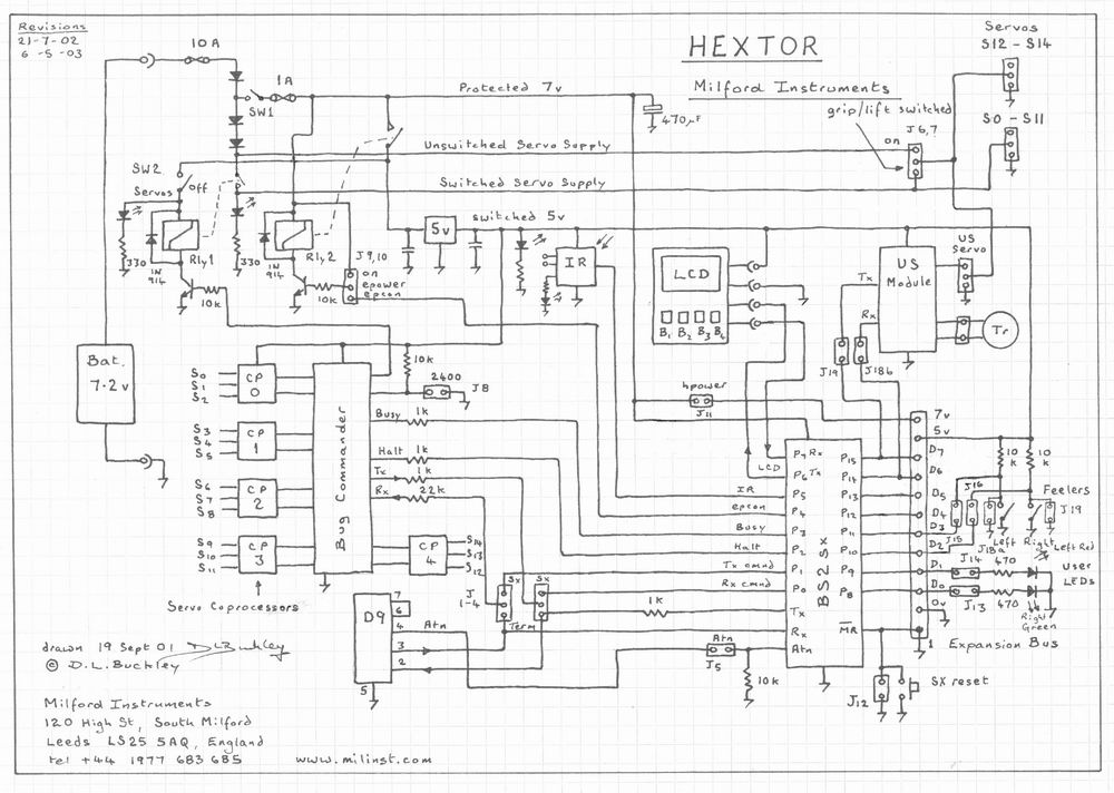
The circuit includes multiple connections for a BOS (Basic Operating System) processor. It has a serial connection for transmitting data to the BOS processor (pin 0) and receiving data from it (pin 1). Pin 2 is used to supply...
There are several websites documenting the original Furby circuit board. I decided to replace the original circuit entirely and replace it with a PIC based controller. The mechanism of the Furby itself was designed around microcontrollers. It has one...
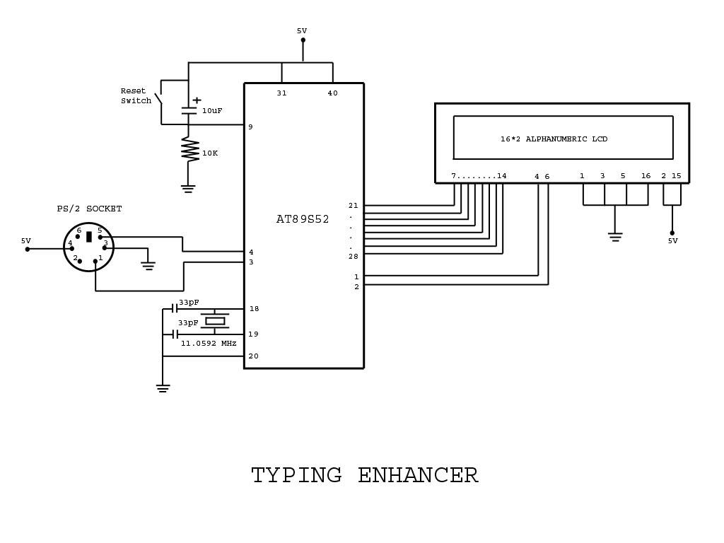
Project with Circuit and Code for a Typing Assistant using the 8051 microcontroller (AT89S52) and the PS/2 keyboard port of a computer. The project also explains the interfacing of the PS/2 port of a computer with the 8051 microcontroller. The...
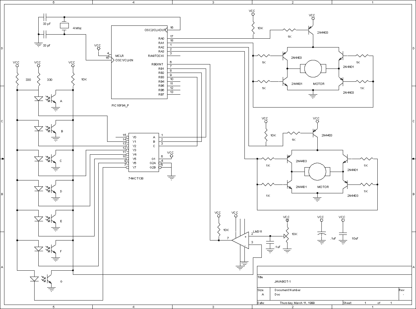
The JavaBot1 is a compact line-following robot engineered to trace a black line drawn on a dry erase board. It is specifically designed to navigate along very narrow curves. The JavaBot1 employs a differential drive mechanism, which allows it to...
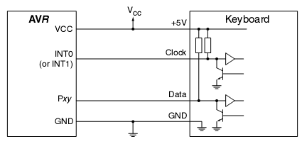
In many situations, a human interface is required for microcontroller projects. This example describes the interfacing of an AVR microcontroller with a standard PC AT keyboard. According to the keyboard timing diagram, the keyboard transfers data to the host...

A mobile-controlled robot is a mobile device that offers extensive wireless control capabilities to the robot, as long as the cell phone remains within signal range. The mobile-controlled robot operates through a wireless communication interface, typically utilizing Bluetooth or Wi-Fi...