
Edge detector

This circuit functions as a pulse generator that reacts specifically to the rising edges of an input waveform. The input signal is first coupled into the circuit via a capacitor, which serves to block any direct current (DC) components, allowing only the alternating current (AC) variations of the signal to pass through. Upon the occurrence of a positive-going edge, the capacitor momentarily charges, causing a rapid change in voltage across the output.
The output pulse's duration is critically dependent on the values of the resistor (R) and capacitor (C) in the circuit. The time constant, defined as τ = R × C, dictates how quickly the capacitor discharges after the initial charging. A larger resistor or capacitor will result in a longer pulse duration, while smaller values will produce shorter pulses. This behavior can be effectively modeled using the exponential discharge equation for the capacitor, which describes the voltage across the capacitor as it returns to its baseline value after the pulse.
For applications requiring detection of negative-going edges, an alternative circuit configuration as referenced in section B should be employed. This circuit would typically involve a different arrangement of components, such as using an inverting amplifier or a different capacitor placement, to ensure that the output pulse is generated in response to falling edges of the input signal. Such configurations can be tailored to meet specific timing and signal processing requirements in various electronic applications.This circuit provides a short negative-going output pulse for every positive-going edge at the input. The input waveform is coupled to the input by capacitor C; the pulse length depends, as before, on R and C
If a negative going edge detector is required, the circuit in B should be used.
Related Circuits
The project demonstration has been successfully completed, with the only remaining task being the final project report due on June 15, which will be integrated with a conference paper. This update marks the last entry in the electronic notebook,...
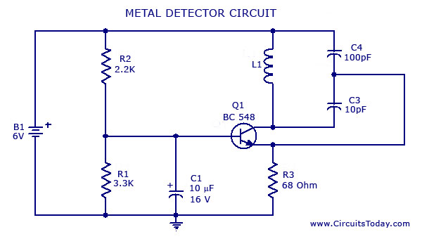
A simple metal detector circuit diagram and schematic using a single transistor and a radio. This metal detector/sensor project is easy to make and is an application of a Colpitts oscillator. The metal detector circuit utilizes a single transistor in...
Portable loads such as video cameras, halogen flood lights, electrical irons, hand drills, grinders, and cutters are powered by connecting long 2- or 3-core cables to the mains plug. Due to prolonged usage, the power cord wires are subjected...
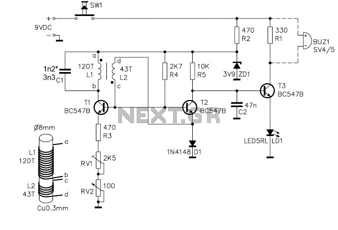
The metal detector circuit comprises an oscillator and a sound-light alarm circuit. The oscillator circuit includes an inductor (L), a capacitor (C1), a sensor switch integrated circuit (IC1) that integrates the oscillator, detector, comparator circuit, and peripheral components. The...
This circuit is a motion detection sensor that utilizes a light source and detector as an infrared motion detector. It incorporates components such as a light-emitting diode (LED), a phototransistor, a transmitter, a receiver, an NE555 timer configured as...
This rain detector alerts users immediately when it starts to rain, providing enough time to close windows and secure belongings. The battery-operated circuit consumes minimal current when the sensor is dry and maintains low current consumption when the buzzer...