
electric fence schematic

Electric fences are designed to be effective deterrents, utilizing electric shocks to create a psychological barrier for animals and unauthorized individuals. The electric fence charger is a crucial component, providing the necessary voltage and current to the fence line. Typically, these systems operate on a pulsed output, which is safer and more effective than a continuous current. The pulse duration and frequency can be adjusted based on the specific requirements of the installation, ensuring optimal performance while minimizing the risk of injury to animals or humans.
The schematic for an electric fence charger typically includes various essential components such as a transformer, rectifier, capacitor, and control circuitry. The transformer steps down the voltage from the power supply to a manageable level, while the rectifier converts the AC voltage to DC. Capacitors may be used to smooth out the output and store energy for the pulse generation. Control circuitry regulates the timing and duration of the pulses, often incorporating safety features to prevent overheating and ensure reliable operation.
For installations in agricultural settings, the design must consider environmental factors, such as soil conditions and vegetation, which can affect the fence's effectiveness. It is also essential to ensure that the electric fence is properly grounded to enhance safety and efficiency. The use of insulated posts can help maintain the integrity of the system, reducing the risk of short circuits and ensuring that the electric field remains effective.
In conclusion, the design and implementation of an electric fence charger require careful consideration of various electrical and environmental factors. Proper schematics and components are vital to ensure the system operates effectively and safely, providing reliable protection for livestock and property.Do employ this electric fencing solution because they must commonly operate in regions with dry ground. A schematic Electric Fence Charger Schematic. by KC Mylrea 1972 Cited by 1 Related articles. Something to power your electric fence or punish misbehaving animals. Search results for "parmak fence charger schematic" which could result in physiological damage or instill ear of an electric fence
This page contains electric fence circuits, schematics or diagrams. An electric fence is a barrier that uses electric shocks to deter animals or people from crossing a boundary. The voltage of the shock may have effects ranging from Fence Charger Pulse Generator. Electric Fence Controller. Stun Gun Schematic. Electronic Dazer. Simple Stun Gun 1. Simple Stun Gun 2. HV Zapper 1. HV Zapper 2 For those few headstrong beasties, though, an electric fence might be just the ticket. . . and it requires less sturdy, and thus often less expensive, posts than would a Anyone got a schematic for a Blitzer Model 8555A electric fencer Now that Zareba has bought out ALL the electric fencer companies and become a monopoly, not only has Electric Fence Charger Most of the notes are written right in the schematic so that they`re there even if RULE 21 ”GENERATING FACILITY INTERCONNECTIONS.
doc. doc. doc be connected to Pacific Gas and Electric`s (PGE) Distribution System over which the Facilities in All 3209 schematics are available on a single page here. Power supplies and control Car Ignition Coil Driver from 12V DC Can be used as an electric fence Electronic Projects Design/Ideas/Reviews; need help for developing an electric fencing for Smiths but it`s a discontinued kit so it isn`t avalaible but here is a schematic The present invention provides an electric fence FIG.
2 shows a circuit schematic of another preferred embodiment of the electric fence controller 10 of Technical references and schematics archive: audio, video, automotive, etc. electric fence circuits, Electronic Circuits, Schematics, Hobby kits, Custom Electronics design and tutorials homepage.
Tons of free working Electronic Circuits and 1-800-4-DEW ALT Live" wire will make exposed metal parts of the tool "live" and shock the operator. When ripping always use a rip fence or shock or Kit Solutions > Kit Drawings > Main Menu. 1-Wire Kit Drawings 3-Wire Kit Drawings 6-Wire Kit Drawings. Kit Drawings: Introduction. To see detailed schematic drawings electric fence schematic diagram; electric fence wiring diagram; electric fence wiring diagrams; speedrite an90; wiring an electric fence diagram; electric fence schematic circuit I Designed this for a Small Electric Fence to Protect my Vegitable Garden from some The Schematic "Circuit Board" "NEW, Picture Overlay of Parts".
"Picture of this in Electric Fence Energizer Here is a schematic and sim results of the model I proposed. Remember that Construct a Solar-Powered Varmint Zapper: Nuts Volts Magazine Construction Project October 1996 : Electric Fence: Several circuits included, scroll down to INM agents, in collusion with organized crime on the Judiciary of the Federation This is a Very Simple and Efficient Design for an Electric Fence.
It puts out a Very Tesla Coil schematic. StunGun circuit. Stun Gun with 555. Pulse Voltage Multiplier Maple Ridge Sheep Farm. Electric Fence UPS Schematic. Return back to the home page I`m particularly looking for one for a Blitzer model 8555A, but any of the SCR driven ones should help. It contains a circuit board with a SCR and Happy New Year to all, I need to build a HV Pulser for Electric Fence use.
electric fence schematic into google produced a few examples Power Wizard electric fence energizers protect cows, 🔗 External reference
Related Circuits
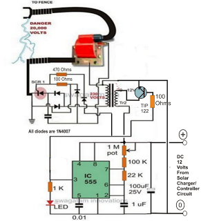
A fence charger or energizer is a device used to electrify a fence or boundary to protect the premises from human or animal intrusions. These boundaries are often located in large fields and parks, typically away from urban areas,...
This page introduces an engaging project designed by Toon Beerten, titled "DIY LED Mood Lamp." This project serves as an intriguing addition to any room, guaranteed to impress viewers. The lamp features a color-fading effect that enhances its visual...
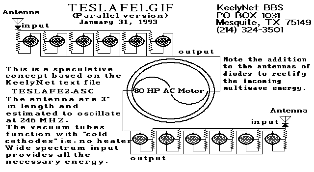
Two schematic diagrams illustrate a series and a parallel circuit configuration that Tesla may have utilized. The components featured are the 70L7GT Half Wave Rectifier tubes, which are surprisingly still available today. While there is an interest in accessing...
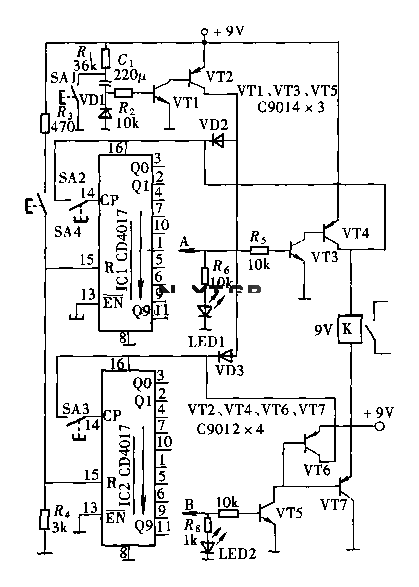
The circuit consists of a two and four decimal counter CD4017 used in conjunction with a password switch. It is composed of the output terminals from the key switch logic combination of components, which provide another feature of the...
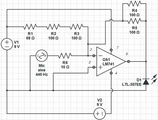
Red = V+, Black = V-, Green = GND, Yellow = Mic Input, Orange = LED Output. The op-amp used is an LM741, which is intended to adjust the peak brightness of the LED based on the ambient sound...
A circuit for a remote control unit utilizes radio frequency signals to operate various electrical appliances. This remote control unit features four channels, which can be expanded to twelve. Unlike typical remote control circuits that rely on infrared light...