
Make this Solar Powered Fence Charger Circuit

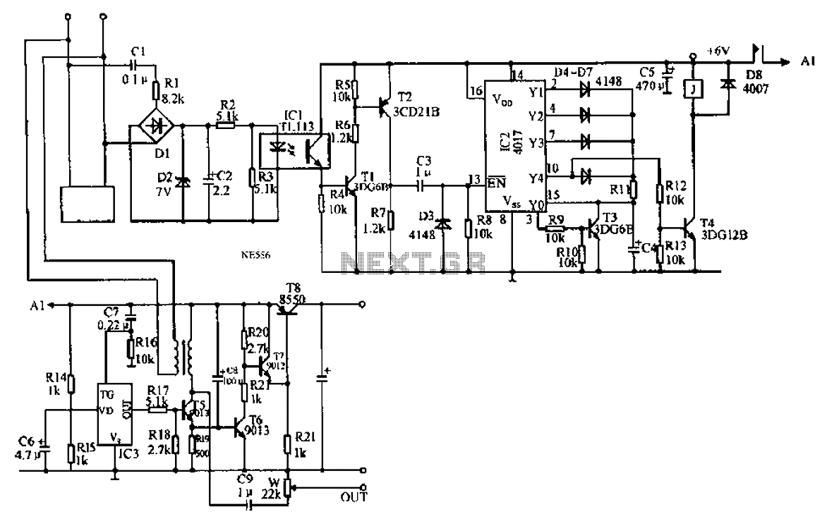
The solar electric fence charger operates by converting solar energy into electrical energy, which is then used to energize the fence. The system typically consists of a solar panel, a charge controller, an oscillator circuit, a transformer, and the ignition coil. The solar panel captures sunlight and converts it into direct current (DC) electricity. This DC power is regulated by the charge controller, which ensures that the battery is charged safely and efficiently while preventing overcharging.
The IC 555 oscillator plays a crucial role in the operation of the fence charger. It generates a square wave signal that is used to control the switching of the voltage from the solar panel. This oscillator is configured in astable mode, producing a continuous pulse output that drives the primary winding of the transformer. The transformer steps up the voltage from the low DC level to a high AC voltage, which is necessary for creating the electric shock that deters intruders.
The ignition coil is a vital component in this system. It is designed to handle high voltages and is responsible for producing the high-voltage output required to electrify the fence. When the transformer receives the pulse from the IC 555 oscillator, it induces a high voltage in the secondary winding, which can reach several thousand volts. This high voltage is then delivered to the fence, creating an electric barrier that is effective in keeping unwanted animals and humans away.
Overall, the solar electric fence charger represents an efficient and sustainable solution for securing remote properties. Its reliance on renewable energy sources not only reduces dependence on traditional power grids but also ensures continuous operation, making it an ideal choice for agricultural and rural applications. The integration of solar technology with effective circuitry design allows for a reliable and environmentally friendly method of enhancing security through electrified fencing.A Fence charger or energizer is an equipment which is used for charging(electrifying) a fence or a boundary in order to protect the inside premise from human or animal interventions. Since these boundaries are mostly of large fields and parks, are normally away from the main cities, and powering them through some renewable option becomes more suit
able than from utility grids which may become difficult to acquire in such remote areas. The circuit of a solar electric fence charger explained here does not depend on traditional power source for operating, rather gets it 24/7 from a self sustained solar power conversion set up. The sudden dumping of the above high voltage inside the ignition coils primary, steps up the surge into several thousands of volts into the secondary winding of the ignition coil.
The triggering circuit consists of a IC 555 oscillator which switches the voltage obtained from the solar panel controller into the transformers input, so that the output from the transformer generates the required 220V AC for powering the ignition circuit. 🔗 External reference
Related Circuits
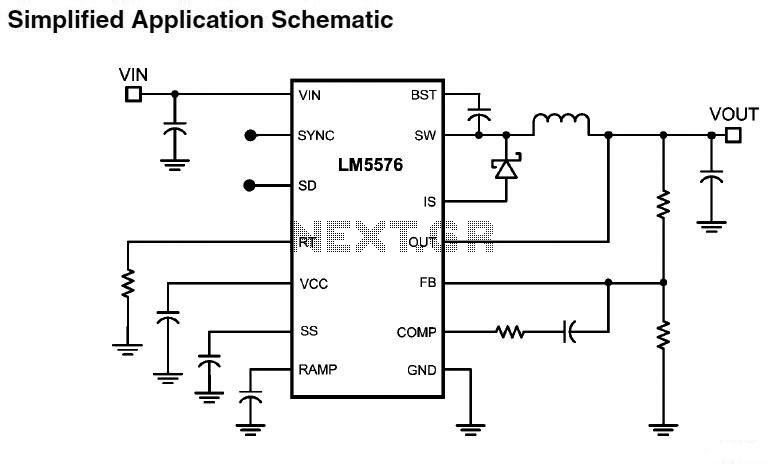
LM5576MHX absolute maximum ratings: (1) VIN to GND: 76V; (2) BST to GND: 90V; (3) PRE to GND: 76V; (4) SW to GND (Steady State): -1.5V; (5) BST to VCC: 76V; (6) SD, VCC to GND: 14V; (7) BST...
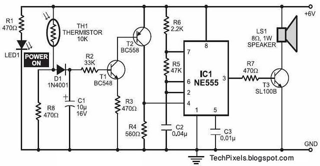
The following circuit illustrates a fire alarm circuit diagram utilizing the NE555 integrated circuit (IC). Features include functioning as a heat sensor and incorporating a 10 kilo-ohm resistor. The fire alarm circuit based on the NE555 IC is designed to...
A microprocessor cannot drive a motor directly since it cannot supply enough current. Instead, an interface circuit is required so that the motor power is supplied from another source, with only control signals derived from the microprocessor. This interface...

The core component of this digital volume controller (DVC) circuit is the IC2 4067, which is a 16-channel analog multiplexer. A 1kΩ resistor is connected between each input and output, allowing the multiplexer to function similarly to a potentiometer....
An automatic recording telephone interface circuit is presented, featuring an automatic answering and recording function that requires a reprovisioning or a small solid-state recording chip. The circuit is straightforward, with a quiescent current of less than 20 µA, allowing...
The schematic diagram originates from a circuit designed for a Car Lamp Charger power supply. The diagram illustrates a Car Lamp Charger circuit, which features a unique characteristic: the battery will not recharge. This circuit is integrated into a...