
nicola teslas electric car revealed

The provided schematic diagrams depict two fundamental configurations of electrical circuits: a series circuit and a parallel circuit, both incorporating the 70L7GT Half Wave Rectifier. This rectifier is a crucial component in converting alternating current (AC) to direct current (DC), allowing for the effective utilization of electrical energy in various applications.
In the series circuit configuration, the rectifier is connected in a single path with other components such as resistors and capacitors. This arrangement ensures that the same current flows through all components, making it suitable for applications where a consistent current is required. The voltage across each component can vary, but the total voltage is the sum of the individual voltages. This characteristic can be advantageous in specific scenarios where voltage division is necessary.
Conversely, the parallel circuit configuration allows the rectifier to be connected alongside other components, providing multiple paths for current to flow. In this setup, each component experiences the same voltage, which can be beneficial for applications requiring stable voltage across components. The total current flowing through the circuit is the sum of the currents through each parallel branch, which can enhance the overall current capacity of the circuit.
The 70L7GT Half Wave Rectifier is notable for its robust performance in low-power applications. Its ability to handle moderate voltage levels makes it suitable for various experimental setups, particularly for those interested in exploring Tesla's historical experiments with electrical circuits. For individuals with limited budgets, acquiring a small quantity of these tubes for experimentation can yield valuable insights into their performance characteristics and potential applications.
In conclusion, the schematic diagrams serve as a foundation for understanding the operational principles of series and parallel circuits utilizing the 70L7GT Half Wave Rectifier. Further experimentation with these circuits can lead to a deeper comprehension of their functionality and practical applications in electronics.There are two schematic diagrams showing a series and a parallel circuit that Tesla could have used. The tubes used were a common 70L7GT Half Wave Rectifer that believe it or notare still available today. I know all of you want to see this site but be patient. Here are the circuit diagrams: Just a suggestion I personally would buy only a couple of these tubes and experiment to see what kind of output that you could
expect to see. I personally have a very limited experimental budget and thus can not experiment as extensively as I would like. Here are some images of the tube. 🔗 External reference
Related Circuits
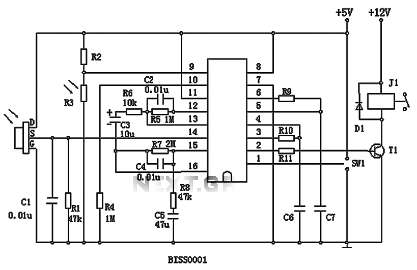
BISS0001 is a high-performance integrated circuit designed for sensor signal processing. It is used in conjunction with pyroelectric infrared sensors and requires only a few external components to function as a passive pyroelectric infrared switch. This circuit can automatically...
The limitation of car supply voltage (12V) forces to convert the voltages to higher in order to power audio amplifiers. This supply is intended for two channels with 50W max each (of course it depends on the amplifier used)....
The total gain of the car antenna amplifier is approximately 30 dB, with an input impedance of around 10 kΩ at 30 MHz. The amplifier should be mounted directly at the base of the antenna to prevent signal losses...
A Transcutaneous Electrical Nerve Stimulation (TENS) device is essentially a machine designed to deliver electric stimulation to the nerves. This device was prescribed to the author. A Transcutaneous Electrical Nerve Stimulation (TENS) device is a therapeutic apparatus utilized for pain...
If the amp is built on bipolar transistors, and the preamp/crossover on FETs, then they were designed by different guys, right? Not this amp. Here, a strong, experienced designer's hand is evident from schematic to parts layout, PCB routing...
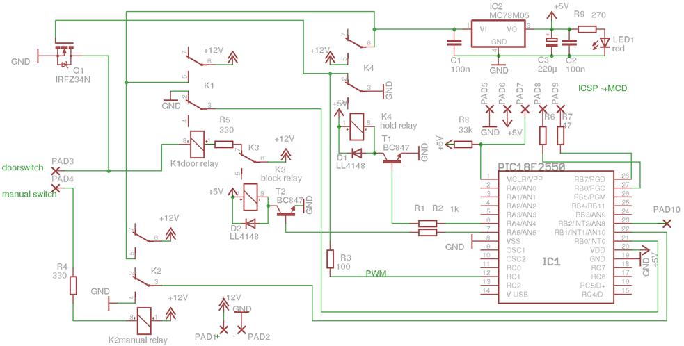
A car courtesy light in a standard vehicle without a board computer functions simply: when the door is opened, the interior light turns on, and when the door is closed, the light turns off. For convenience, it is beneficial...